Hi,
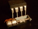
When they arrived I discovered that the plastic 'nut' is not threaded, it just slides freely along the drive rod.
----
...has anyone any ideas as how I could make these useful ?
Yes, I found the same - the "nut" is so loose that I doubt if it's "broken", but another component part is required. I pushed a piece of 30 awg copper wire under the "hook" which locks the nut onto the shaft to see how it's rotating. But it will need something finer than that for the screw to move the nut along the 1mm diameter shaft.
Also, perhaps I should have realised that the "outrigger" arm carries the second motor bearing, so it can't be removed to use the shaft with a normal worm/pinion gear at the end. I have some ideas how to couple (rotary) motion from the motor, but I've found that theory doesn't always work with these little steppers, so I need to experiment first.
However, I do know how to drive them at a cost of 20 pence and two PICaxe pins
")
. I started a thread a few weeks ago
here and will add to it when I've devised some reasonable hardware and software configurations. The easy-to-use board can drive at least two (perhaps 4 or more) of these steppers with coils in parallel, since each coil is around 24 ohms.
The way I propose to make (reliable) electrical connections is to glue the back of the foil "cable" onto the motor body with Araldite (epoxy resin) and when set, cut off the surplus foil and solder 30 awg wires directly onto the pins. This motor and the one in my link both have 20 steps per revolution. They seem to work "best" with both coils energised "continuously" (i.e. a current reversal in one of the coils for each step) but the heating at even 3 volts is probably too high for anything more than short periods of operation. They do rotate with individual (even separated) pulses to each coil but it depends how much output "power" (or torque) is needed.
___
I think these really tiny motors are mainly going to be useful for "indicator" type applications. But I still have high hopes of using two of the slightly larger (6 mm) version shown in my link above to drive my (proposed) "AA" (cell) line follower, using differential steering / sensors. The "chassis" is a piece of Vero/perfboard 21 holes by 6 (52 mm x 16 mm) carrying a (DIP) 14M2. Actually I believe an 08M2 might be sufficient, but I want to retain the option of using it as a test bed to carry a "camera" based around edmunds' linear optical sensor.
Cheers, Alan.
 192.4 KB Views: 71
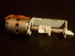 166.7 KB Views: 72