Are you sure this is a good subject, for your first major Picaxe project?
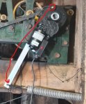
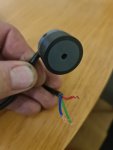
Really good question, i came to picaxe as a route to make the manufacturers product better over an above the 555 timers i had been using for 12 months previously which were a huge improvement on the issues they were having previously, if you look at my first project on here titles "switching issues" that is the picaxe control set up i have designed to replace the 555 timer and it has additional fail safe features beyond what i could do with the timer in the space i had to fit it all, there is a limit switch should the motor move too far, if you look in the picture above you will notice a black cord attached at one end to the clock stand and at the other to the end of a white nylon plug that you will see goes through and out of the control box on the motor, if it drives too far the plug is pulled out and that removes all power to the motor, in the control circuit it is fitted after all control circuits and before the motor, so is the fail safe and this has been in the manufacturers units for many years i understand.
So all in all i think the picaxe is an improvement and with the huge help i have had from several members of the forum i am happy to put my mane to my involvement in the project.
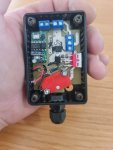
Before i became involved the motor junction box had a row of 5 connector blocks, a micro switch and several smd components soldered in a lump and shrink sleeving all pushed into the box, now we have a pcb that fits snugly in the box with a pcb terminal for every wire in the position they enter the box, space on the pcb to lay the smd components out correctly, a set of 4 header pins for the timer pcb to sit on, which will be replaced with the picaxe version.
Previously the system at the power supply had a low voltage cut off setup to protect the battery from deep discharge, this was a 4 pole relay with a pot inline with the supply and a push button the set the latch set-up, the relay used to drop out around 10.5v, but the relay used 65ma and dureing mains fail was using quite a lot from the battery over the 168 hours a church would ideally want but never managed.
I altered this design to a 555 using its comparator driving 2x P-channel mosfets which brought the running current down to about 12ma, i could see with picaxe i could move a step further and have voltage monitoring being done by the picaxe along with its timing duties, this reduced the standby current hugely.
As it was with 3 drive units on a quarterly chiming turret clock, with the 555 based control system and low voltage cut off the standby current was around 52ma, going over to picaxe this should reduce to around 4ma max, when on battery the control system now takes about 600mah from the battery during the wanted 168hr backup whereas before the main current draw on the battery was the control system not the motors and the reason they never got the back up they wanted.
It seems if the code is good then the reliability of the picaxe is better than any previous set ups
 ...
...