The power of Midi

Hi all !!

Just a couple of quick question's before i continue on my project of building a musical control surface for my computer using a pic.

Firstly Is it possible to use a picaxe 28X or 28x1 for midi ? :confused:
If not please can somone please post a list of avaliable chips to use.

Secondly Is there a certain output pin on either of these devices that must be used to connect to the midi socket?

Thanks !

Alex
 

hippy

Ex-Staff (retired)
The X1's and X2's will all allow MIDI output at 31250 baud using HSEROUT. By poking SFR's an 18X that can do MIDI but that's a poor choice these days.
 
Ok Im going to use a 28X1 chip then

1 more thing, it says that an external resonator is not required for the X1 and X2 parts. Do i need to tie the pins to ground or can i just leave them floating ?

Cheers !
 

hippy

Ex-Staff (retired)
Do not connect either to ground or 0V. You can leave them floating. For best low-power operation I recall it being suggested that a 100K (?) should be used to tie down XIN to 0V.
 

hippy

Ex-Staff (retired)
On the 28X1, leg 9 is OSC1/CLKIN ( what I called XIN ). You have to look in the PICmicro datasheets for that.
 

inglewoodpete

Senior Member
I'd suggest you prove the concept on breadboard before making a PCB. All too often, little 'gotchas' sneak up on you when you least expect them.
 
The next stage...

Hi all ! :rolleyes:

I prototyped the circuit and simulated an input and output test on the computer and have got the PCB made.

I am just waiting for my chip to arrive (hopefully tomorrow) :D

But, on the forums somewhere (i stumbled accross it the other day and now cannot find it again !!!) there is a link to a piece of software that i cannot remember the name of that reads midi data comming into the computer.

I need this because im not quite sure how you use the hserout command to work out what midi value or controller it assigns too. (im am building a contol surface for a music editing program and wish to turn controllers on and off remotely with this interface)((if a piano can do it a pic can !!)) :confused:

Im so easily confused !! :confused:

But i will probably get it after a bit of playing around

Any advice appreciated !!

Thanks !!

Alex !!!
 
:D:D thats pretty much exactly what im after by the looks of things.

Thanks very much !!!

I have build the PCB and am currently in the process of downloading the latest programming editor as my version doesnt support the 28X1 chip :confused: :confused:

Very odd !!
 

MPep

Senior Member
It always pays to get the latest version, as minor bugs (or in your case complete PICAXE versions!:D) are constantly being fixed, new features added.
 

hippy

Ex-Staff (retired)
Perhaps a bit late in the day, but here's an untested keyboard scanner to MIDI output for PICAXE-28X2. Should also work on the 28X1 with some cahnges. Port C are output strobes, Port B are inputs, keyboard wired as a standard diode key matrix, inputs pulled down. Supports 6 x 8 keys, 48 in total, 4 octave. Can get more by using Port A as additional strobes.

Loop time when nothing is pressed is around 3ms at 32MHz so average latency will be 1.5ms; that shouldn't be a problem at all. Handles multiple key presses, no key velocity - might want/need to change the $7F velocities for Note On's to $3F for a nicer sound.

Wiring for the "MIDI Out" 5-way DIN is; pin 4 and 5 each via 220R, one to TX ( leg 17 ) the other to 0V or +5V. Not sure which is which; swap and change and two out of the four combinations should work.
 

Attachments

Programming

Hi !

I have made the interface and its all wired up and working, Apart from the whole midi side of it !! :mad: (and i havent tested the potentiometers yet)

I have wired the soket up in the following way, As shown on hippys website :D
http://homepage.ntlworld.com/the.happy.hippy/picaxe/midiuart.txt

And i know how to use the hserout comand eg:
hersout 0,($80, $00, $00) should be all notes off.

But im not quite sure how the hsersetup works !
Has anyone got a simple test program that just sends a message via midi in a loop so i can see if it works and test it out !

I know the midi on the computer is working as i have plugged in a keyoard and checked the messages are comming through using the program shown earlier in this thread (which is great thanks!)

1 more thing, how do i specify what channel the midi is using if its possible ? (1 to 16)

Thanks !!

:confused: Alex
 

slimplynth

Senior Member
Hi Alex

Just one observation on your code you have

"Midi:" as a subroutine

but reference it as "goto midi" (lowercase m)

Edit: please disregard - sorry, in PE simulator - uppercase or lowercase is ignored...

Code:
main:

high 1
pause 1000

goto ledlow

Ledlow:
low 1
goto main
so the above works
 
Last edited:
Program

So The following ammended version of the program should work in theory...(when i try it after i get home from school)

So how do you work out what each of the codes for the commands are ?
Like sustain controllers etc

Also, would it be better to run the chip at 4 or 8MHz for this operation?

Thanks for all the help guys ... im finding this a bit confusing !! lol

Alex
 

Attachments

hippy

Ex-Staff (retired)
Your program would best be ...

#Picaxe 28X1
#No_Data
#No_Table
HSerSetup B31250_4, %000
Pause 500
Do
HSerOut 0, ( $B0, $7B, $00 )
Pause 1000
Loop

Ideally run as fast as possible, but get it working with default clock speed first.
 

lbenson

Senior Member
And for more eyeballs on your code, don't attach it but put it in your message between [code]...[/code]
 
Still not working !!

Hi guys !

Last night i checked over the whole circuit again and also ran a whole test of the inputs, outputs and sertxd command just to check the chip was running correctly and could send data to the computer.

But in stillnot managing to recive midi data into the computer using that program posted earlier by hippy
I have checked the picaxe socket is wired up correctly and sometimes when i press the hard reset on the chip unrecognised midi type data is sent to the computer so i know it is working.

So now im lost !! whats can i do next ? :eek:

Im running the chip with 3 AA batterys if that makes any difference?!

Thanks !

Alex :confused:
 

hippy

Ex-Staff (retired)
Post, or describe, your circuit diagram with respect to PICAXE to MIDI Out connector.

You can try changing to "HserOut B31250_4, %010" which may resolve any simple polarity errors.

You can also try changing to ""HserOut B4800_4, %010" and to "HSerOut 0,("ABC")" and seeing if that can be received ( from the PICAXE TX leg ) to a PC.
 

vttom

Senior Member
Hi guys !

Last night i checked over the whole circuit again and also ran a whole test of the inputs, outputs and sertxd command just to check the chip was running correctly and could send data to the computer.

But in stillnot managing to recive midi data into the computer using that program posted earlier by hippy
I have checked the picaxe socket is wired up correctly and sometimes when i press the hard reset on the chip unrecognised midi type data is sent to the computer so i know it is working.

So now im lost !! whats can i do next ? :eek:

Im running the chip with 3 AA batterys if that makes any difference?!

Thanks !

Alex :confused:
Here's a thought....

Try a simple program and circuit that sends data out of the PICAXE at a standard data-rate (eg 9600 bps), connect it to a regular serial port on the PC, and bring up a terminal program (eg Hyper Term) to observe the output.

This will allow you to "divide and conquer", and get the serial communications part of it robust before tackling MIDI.
 
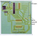
Here is the PCB layout and circuit diagram is on this page:
http://www.facebook.com/album.php?aid=157473&id=742039391&saved#/photo.php?pid=3788437&id=742039391

(if it doesnt work give me a shout but they are both there in a bigger size)

When you say send the hserout command via the normal TX leg ... do you mean via the programming cable ??

Because i can already send serial data back to the computer via the programming cable as i have checked that (i will check the commands when i get home )

hope it all makes sense !
 

Attachments

hippy

Ex-Staff (retired)
Can't get to FaceBook without creating an account, so somewhere else openly accessible would be preferred.

To connect the HSEROUT to a PC you need to unplug the download cable, and for the 3.5mm jack; connect the tip to 0V, leave the ring unconnected, and connect the sleeve direct to leg 17 of the PICAXE 28X1, this is the leg which HSEROUT sends data through.

Added : Looking at your circuit diagram it's not clear if you have leg 17 connected to the MIDI Out.
 
Last edited:
leg 17 ???

You have just spotted the mistake im making ;)

Now i feel silly lol !!!

I have attached the midi out pin to OUTPUT 6 of the chip and not INPUT 6 ... just looked at the pinout diagram again and realised :p very silly mistake !!!!

So sorry !!!!

I will go change my set up temporarily to see if it works and then manufacture another PCB accordingly

Sorry for all ther bother over a silly mistake !!!

Get back to you soon !!!

Alex
 
Hi all !!!

The Project works brilliantly now !!!
Its talking to the computer via serial and midi and i have managed to map all the controls to buttons etc.

But. The potentiometers have vales from 1 - 255
and a midi controller has a value from 0 - 127
So when i turn the potentiometer on when it gets half way the controller on the computer is full on

I need a way of making it so when the value goes up for down by 2 it sends the correct number out ( if that makes any sense )

Thanks for all your help !!!
#Alex
 

hippy

Ex-Staff (retired)
@ Alex : A simple one this and you'll kick yourself; simply divide the reading from ADC by two ...

ReadADC pin, b0
b0 = b0 / 2
 

vttom

Senior Member
But. The potentiometers have vales from 1 - 255
and a midi controller has a value from 0 - 127
So when i turn the potentiometer on when it gets half way the controller on the computer is full on

I need a way of making it so when the value goes up for down by 2 it sends the correct number out ( if that makes any sense )
Couple of things to consider:

1) Are your potentiometers linear or "tapered"?
2) Are they directly controlling an audible "volume", or just a "sound parameter".

If you are using a potentiometer to directly control volume (like the knob on your stereo, or a knob/slider on a mixing panel), then you should either use a tapered potentiometer, or a linear potentiometer and apply the logarithmic taper in software.

The reason is that humans perceive sound volume on a logarithmic scale: The louder the sound, the larger a delta you need to make to it in order to perceive the change / The quieter the sound, the less of a delta you need to make to it in order to perceive the change.
 

pbaker21

Senior Member
Can anyone give me an outline in layman’s terms (if possible) on how ‘hSerPtr’ reads bytes and how I can somehow break these apart to use their bits(!!?).

I’m currently playing around with Midi data and can send volume data to my sequence from my picaxe no problem, in fact it works great! My real problem is, understanding how to deal with in coming data to my picaxe chip (20x2).

I have been given code from various users (many thanks) and have trawled the web which I think has helped a lot. I guess I’m trying to approach my ‘hSerPtr’ problem a different way.

Thanks.
 

hippy

Ex-Staff (retired)
'hSerPtr' is simply a pointer to where the receiving on-chip UART will next place a byte received. It's best to leave 'hSerPtr' alone and 'chase that' with 'ptr' to extract the bytes which are in the buffer. This is the basic code for doing that, setting b0 to each byte received in turn ...

Code:
hSerSetup ...
ptr = 0
Do
  If ptr <> hSerPtr Then
    b0 = @ptrInc
    :
  End If
Loop
With the received data in 'b0', you can then forget about 'ptr' as well as 'hSerPtr' and deal with 'b0' as you would for data received from anywhere.

For MIDI data it's a bit more complicated than a stream of bytes as different values mean different things, you need to also track those values to determine what you have but at the end of that process you will still have data in 'b' variables and can again forget about the 'ptr' and 'hSerPtr'.
 

pbaker21

Senior Member
'hSerPtr' is simply a pointer to where the receiving on-chip UART will next place a byte received. It's best to leave 'hSerPtr' alone and 'chase that' with 'ptr' to extract the bytes which are in the buffer. This is the basic code for doing that, setting b0 to each byte received in turn ...

Code:
hSerSetup ...
ptr = 0
Do
  If ptr <> hSerPtr Then
    b0 = @ptrInc
    :
  End If
Loop
With the received data in 'b0', you can then forget about 'ptr' as well as 'hSerPtr' and deal with 'b0' as you would for data received from anywhere.

For MIDI data it's a bit more complicated than a stream of bytes as different values mean different things, you need to also track those values to determine what you have but at the end of that process you will still have data in 'b' variables and can again forget about the 'ptr' and 'hSerPtr'.
So, if I were to output with 'SerTxd' I'd see a constant stream of bytes quizzing past, when Midi data flows?

If ptr <> hSerPtr Then
b0 = @ptrInc
SerTxd..blah blah
End If

I'd then have to decipher these values i.e. midi channel etc...?

Thanks.
 

pbaker21

Senior Member
I did try "So, if I were to output with 'SerTxd' I'd see a constant stream of bytes quizzing past, when Midi data flows?"
And it worked as far as retuning about 30 bytes then stopped, until I hit the play button again on my sequencer and it just repeated the same again.

I'll take a look at the attachment - many thanks.
 

hippy

Ex-Staff (retired)
it worked as far as retuning about 30 bytes then stopped, until I hit the play button again on my sequencer and it just repeated the same again.
There could be a number of reasons for that, including that being all the sequencer sends !

The best way to start is as simple as possible; with the PICAXE showing what comes from a MIDI keyboard, then just press and release keys to see if that works okay.

Once happy with that, you can move on to looking at more advanced and complicated stuff.
 
Top