Technical help, new user to picaxe

ausiey

New Member
Technical help, new user to picaxe
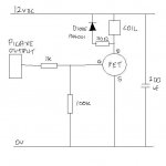
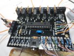
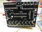
I have recently built my first project link below and all went Ok including the assembly, programming and testing using LED as indicators on the outputs, the outputs are driven by Mosfet transistors, the fault arises when I connect a relay or a dummy load at the output, the output voltage at the output which is 12v drops to 0 volts as if I put a dead short across the output, Thanks in advance for any suggestions.
Link http://www.rkeducation.co.uk/documen.../RKP28inst.pdf

Answer your question nick12ab and hopefully i am in the right area for posting my query.
The leds were connected after them.
The dummy load is a 10 ohm 10watt resistor and is connected across the drain and the positive 12 volt rail as in the cct in the link
 

bfgstew

Senior Member
Cheers Nick.

Shouldn't there be a 10K pulldown resistor between the output pin to ground on the FET gate?
 

rossko57

Senior Member
the output voltage at the output which is 12v drops to 0 volts as if I put a dead short across the output,
Could you clarify where you are measuring, and with reference to what? The FET output terminal is supposed to go low when "on". (The other load terminal should remain at +12V)
 

ausiey

New Member
The output is measured between a 12v positive and the switched negative.
There are two voltages coming form one source, the 12v and a regulated 5v, I even tried connecting two different sources such as a 12v battery and a 4.5 v battery.
I tested the MOSFET on a separate CCT and its Ok.
 

nick12ab

Senior Member
Have you programmed the PICAXE to make the MOSFET turn on?

Have you put the MOSFETs in the right way?

Can you post a photo of the top and bottom sides of the board?

You say that it goes to 0V when a small-ish load such as a relay is attached. Can you connect a multimeter set to the amps range to the output and find out how much current there is?
 

westaust55

Moderator
@ausiey,

welcome to the PICAXE forum.

Are the diodes installed in the correct orientation? That is with the white band towards the terminal strip.
If reversed, then when the FET is turned on, there is a short across the supply.

As bfgstew has mentioned, although I am no FET guru, I believe a better circuit would have a pull down resistor between the FET gate and ground.
This would help with FET turn off and prevent the gate floating when the PICAXE pins are inputs during power up/initialisation for a 28X1 or until set as outputs for a 28X2 part.
In fact it raises the question, exactly which microcontroller chip are you using with that non Rev Ed board.


Certainly, a photo of the project board would help.
 

inglewoodpete

Senior Member
The output is measured between a 12v positive and the switched negative.
There are two voltages coming form one source, the 12v and a regulated 5v, I even tried connecting two different sources such as a 12v battery and a 4.5 v battery.
I tested the MOSFET on a separate CCT and its Ok.
Tell us more about the 12 volt battery. What type (make/model) and capacity is it? There is probably something wrong with the battery if the voltage collapses and nothing starts to smoke when you turn on the FET with a 10 ohm load.
 

ausiey

New Member
Hi Nick12ab
Yes the picaxe is programmed correctly because the test leds work Ok.
The Mosfet are the right way otherwise they would not switch the negative/ground to the output.
The photo of the board is on the link.
I cannot measure the current because it happens to quickly.
 

nick12ab

Senior Member
The photo of the board is on the link.
A photo of your board would indicate whether poor soldering or wrongly inserted components is the problem. A picture in the datasheet does not.

I cannot measure the current because it happens to quickly.
Do it with the multimeter connected and nothing else. Set it to the highest amp range it goes to.
 

ausiey

New Member
Hi inglewoodpete
I thought the same about the battery, so I replaced it with a 12v car battery that is in good condition.
 

ausiey

New Member
New Camera Pics 220.jpgNew Camera Pics 222.jpg

Hi Nick12ab
I think I have uploaded and attached the pic's you required, I will let you know about the current reading another day.
 

inglewoodpete

Senior Member
Hi inglewoodpete
I thought the same about the battery, so I replaced it with a 12v car battery that is in good condition.
Car battery! If that's in good condition then things should happen. What happens to the terminal voltage across the battery when the MOSFET is turned on, even after a few seconds or a minute.

A 10 ohm resistor should result in a current of at least one amp. The resistor will get pretty hot, pretty quickly! If the battery voltage is remaining at 12 volts and the resistor is not getting very hot then either the MOSFET is not turning on properly or the circuit is wired wrong.
 

Goeytex

Senior Member
A manufacturer's brochure photo does NOTHING to help us troubleshoot your problem.
The request was for clear closeup photos of YOUR actual board, of the top,
and of the bottom.

It we assume that the kit is properly designed and no parts have failed, then it only
stands to reason that the problem is the result of something you did or didn't do.
Clear photos can help us find the problem.

If you are unwilling to take the time to take and post these photos, then I doubt
there is much else folks can do other than guess.
 

westaust55

Moderator
The photos posted at post 17 suggest the FETs and free wheeling/flyback diodes are correctly orientated.

What are the wires doing soldered to the underside at a couple of the FETs rather than via the terminal strip?

A photo taken perpendicular to the PCB provides the best opportunity for others to look for faults.
For example there appears to be a big dollop of solder bridging two pads where the 0utput 0 FET has been removed. Why was FET removed?
 

Dippy

Moderator
Are you measuring across the TB only?
Have you tried measuring (for example) TB1.1 down to ground and TB1.2 down to ground?

If only measuring across TB1 (for example) , with a low res load, you will measure 0V if the MOSFET is off.

Have you tried measuring V at 'OUT1'?
Have you buzzed out the PCB to check connections?
Have you checked your MOSFET pinout compared to PCB?

Whip out the PICAXE, power up the circuit and poke 5V to (e.g.) OUT1 and repeat the measurements.
(Best via a resistor to prevent a big poof).

Other than bad code/wiring/soldering I can't see why it shouldn't work.

I see the label for the PIC is a competitor that is unpopular with Rev-Ed...
I assume it's definitely a PICAXE you are using? ;)
 

rossko57

Senior Member
I see the label for the PIC is a competitor that is unpopular with Rev-Ed...
I assume it's definitely a PICAXE you are using? ;)
Interesting ... I have bought in one of these very kits with 28X2 for a project. As yet unmade, so no real help here; I do not yet know exactly what's in the supplied PIC (mine is marked same as ausiey's). Surely not a suggestion it is a fake PICAXE? It is not branded PICAXE, but I just assumed it pre-dated the 'stamping'.
 

westaust55

Moderator
Interesting ... I have bought in one of these very kits with 28X2 for a project. As yet unmade, so no real help here; I do not yet know exactly what's in the supplied PIC (mine is marked same as ausiey's). Surely not a suggestion it is a fake PICAXE? It is not branded PICAXE, but I just assumed it pre-dated the 'stamping'.
A firmware test from within the rev Ed Programming Editor (under the Options sub menu) will ascertain the exact chip type, if a Rev Ed chip.
 

nick12ab

Senior Member
Interesting ... I have bought in one of these very kits with 28X2 for a project. As yet unmade, so no real help here; I do not yet know exactly what's in the supplied PIC (mine is marked same as ausiey's). Surely not a suggestion it is a fake PICAXE? It is not branded PICAXE, but I just assumed it pre-dated the 'stamping'.
What stamping? Only M2 parts are stamped with a PICAXE name - other parts have the PIC part number on. The chip in the socket (in the picture) is marked PIC18F25K22 so is a 28X2.

The website suggests that no PIC is included and you have to supply your own.
If a chip was supplied with the board, if it's marked PIC16F883 then it's a Genie chip but if it's marked PIC16F886 then it could be a ******* or PICAXE and you'll need to check it with the firmware checker. A PIC18F25K22 or PIC18F2520 is a PICAXE-28X2. It could be a blank PIC though so you should still check it.
 

Goeytex

Senior Member
Troubleshoot the MOSFET as follows.

1. Power Off
2. Remove the Picaxe or whatever chip is in the is in the socket
3. Connect a 100 ohm resistor across TB1.
4. Put a 1K ohm resistor between the MOSFET gate and +5v
5. Power On
6.With Meter common connected to ground, read & record voltages at TP1, TP2 & TP3

7. Power Off
8. Connect the 1K resistor Between the MOSFET gate and ground
9. Power On
10. With meter common connected to ground, read & record voltage at TP1, TP2, & TP3
11. Post results here

Refer to Diagram below as needed.
 

Attachments

ausiey

New Member
Hi all
I have solved the fault, I have never run into this type of fault before.

Short explanation.-- Mosfet IRF501 need to have 5v at the gate to operate properly, my circuit was providing 3.6v and it would operate a small load but for some reason the mosfet would reset under a heaveir current draw load, I increased the supply voltage to he picaxe to 6 v and this made the mosfet operate correctly.

Long answer--- The fault was the switching voltage to the gate of the Mosfet, The picaxe chip was powered by a a 5v regulator circuit whose source was 12v, when the output of the 5 v regulator was measured it was 4.62 Volt and this powered the picaxe and it seemed to operate properly, the output pin of the picaxe when high was 3,6 volts this was also at the gate of the mosfet and it would operate and drive the led but when a heavier load was connected to the mosfet, the mosfet would reset. But when the mosfet had a 5v connected to the gate it would operate and stay operated even when a heavier load was connected. So I increased the supply voltage to the picaxe to 6v and this made the output of the picaxe when high produce 4.95v, this seemed to latch the mosfet and drive a heavier load.

A lesson learned an to keep in the memory banks, but these days the memory doesn't operate as well, I blame the years, and overload of info sometimes.
Thanks for all your help.
 

nick12ab

Senior Member
Short explanation.-- Mosfet IRF501 need to have 5v at the gate to operate properly, my circuit was providing 3.6v and it would operate a small load but for some reason the mosfet would reset under a heaveir current draw load, I increased the supply voltage to he picaxe to 6 v and this made the mosfet operate correctly.

Long answer--- The fault was the switching voltage to the gate of the Mosfet, The picaxe chip was powered by a a 5v regulator circuit whose source was 12v, when the output of the 5 v regulator was measured it was 4.62 Volt and this powered the picaxe and it seemed to operate properly, the output pin of the picaxe when high was 3,6 volts this was also at the gate of the mosfet and it would operate and drive the led but when a heavier load was connected to the mosfet, the mosfet would reset. But when the mosfet had a 5v connected to the gate it would operate and stay operated even when a heavier load was connected. So I increased the supply voltage to the picaxe to 6v and this made the output of the picaxe when high produce 4.95v, this seemed to latch the mosfet and drive a heavier load.
Where abouts was this 4.62V measured? Was it before or after the diode on the board?

Since the PICAXE would only produce 3.6V on an output pin (which seems a bit low), that suggests that this is before the diode. In that case, there's some problem with the regulator or the board? What regulator are you using? If it's a linear regulator does it get hot?

The MOSFET should only require a maximum of 4V so if the regulator is working fine and you short out that diode (diodes with big voltage drops in series with low voltage circuits are never helpful) you won't need to use whatever was supplying 6V.
 

hippy

Ex-Staff (retired)
The picaxe chip was powered by a a 5v regulator circuit whose source was 12v, when the output of the 5 v regulator was measured it was 4.62 Volt ... the output pin of the picaxe when high was 3,6 volts
There seems to be something wrong for both cases; a 5V regulator producing substantially less than 5V and the PICAXE dropping such a large amount internally.
 

bfgstew

Senior Member
Defo something amiss somewhere. My circuits are 12VDC source through a 5VDC regulator circuit and produces a steady 5VDC. Also no problem with running a MOFSET with a hefty solenoid coil on it. I still think the missing pulldown resistor will help.

fet.JPG
 
Top