Tearing my hair out with 14M2 circuit to drive two servos

abenn

Senior Member
Having sorted the issue I raised in my previous post about a 14M2, I now have a circuit board with a jumper so that pin c.5 can be switched for programming or running. But my circuit is still not behaving as I expect.

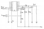
Two simple on/off toggle switches are connected to pins c.3 and c.5 (the latter via the jumper) via a 10k/1k resistor network as per the standard input circuit at the bottom of p26 of the manual -- with the 10k connected to +5v.

Two standard RC servos are connected directly to pins b.0 and b.1, and the servo power leads are also connected directly to +5v and ground.

The AXE027 programming lead is connected to C.5 (serial in) via the jumper, B.0 (serial out) and ground, with resistors as per the manual, and works okay.

Nothing is connected to the other 14M2 pins at the moment, other than +5v and ground.

My simple test program is as follows:-

Code:
init:

	servo b.0,150
	
main:

	if pinc.5 = 1 then
	  servopos b.0,175
	else 
	  servopos b.0,125
	endif
	pause 2000
	goto main
My problem is that whichever pins I specify in the code, nothing works properly:-

C.3 input and B.1 servo operate as expected if the jumper is in programming position, but not with it in the run position;
All other combinations of C.3, C.5 servo and B.0, B.1 input result in the servo just jerking back and forth at about 1-second intervals, whichever way the switch is set.

I've checked and re-checked my circuit board which, as I said in my previous post, is basically a copy of one I have running with an 08M2, but with extra pins which I need for future extra functions. Any ideas what's going on, please? The program loads okay, but could it still be a damaged 14M2? Unfortunately I've soldered it in, rather than using a socket, so swapping it for another one will probably destroy it.
 

cravenhaven

Senior Member
It would probably be helpful to have a cct diagram of your hardware, but for a start dont you need a 'disconnect' command if you are using the serial-in/out pins for other purposes?.
 

Technical

Technical Support
Staff member
C.5 is a poor choice of input, it will constantly reset your chip as it is the serin pin (without a disconnect command). Try to avoid it completely if you can use any of the other inputs.
 

erco

Senior Member
... don't you need a 'disconnect' command if you are using the serial-in/out pins for other purposes?.
+1. Suggest you start by NOT using the SERIN/OUT pins. Use any other pins to nail function first. Only then, transition one pin at a time to use C.5 and then B.0. C.5 must always have a pulldown resistor on it, and per cravenhaven you'll need to use DISCONNECT and hard resets from then on to reprogram. So C.5 is only useful an an input when it is switched high.

Using B.0 as an output is less problematic. It can drive a servo or something else, but expect glitching during download, and SERTXD will likely print garbage on your screen if anything is connected to it.

If you're cramped for pins, why not use a 20M2 if you have room for it? Negligible cost increase and it's worth it just to avoid hard resets.

See my post at http://www.picaxeforum.co.uk/showthread.php?29282-DISCONNECT-Saves-the-Day
 

abenn

Senior Member
Thank you for your comments. I thought C.5 was okay because it's shown in the manual as "(In) Serial in".

I've just tried using the DISCONNECT command at the beginning of the program and, while it seems to solve the problem with C.5, I'm still getting only twitches and no action from the servo that's on B.0 that's operated by the switch on C.3.

Sorry about the lack of diagram, I'll post one later today. But I do have a plan B which avoids using C.5, albeit with the loss of one output, which I think will still be okay for my purpose. Otherwise I'll redesign it to use a 20M2, as suggested.

Edit: Here's the diagram

ScanImage001.jpg
 
Last edited:

eggdweather

Senior Member
Have you tried a simple program:
init:
servo b.0,150
main:
servopos b.0,175
pause 2000
servopos b.0,125
pause 2000
goto main

This checks if the servos are working as expected.
 

hippy

Technical Support
Staff member
Download Serial In (C.5) needs to have an active high signal in order to allow it start properly, and needs to be low before the program can execute the DISCONNECT command.

You have an active low button on C.5 which will cause problems. What you are probably seeing is the effect of the PICAXE continually resetting because it is expecting a download.

The following shows how it is recommended C.5 should be used for button input -

http://www.picaxe.com/FAQs/Interfacing/#q9
 

darb1972

Senior Member
abenn, are you using any/all of the remaining pins on the 14M2 shown in your schematic? If not, as others have suggested, why not steer clear of C.5 and use another pin? It would certainly reduce the potential complexity.
 

abenn

Senior Member
The remaining pins are destined to eventually be connected to a Darlington array to control eight other outputs, but are not connected to anything at the moment.

I'm going to take the advice to avoid using C.5 (and B.0) for anything other than programming, either by managing with only six other outputs (favourite), or by using a 20M2 -- its pin layout seems similar enough to the 14M2 that I can easily extend my board design to use it.

Thanks for all the help.
 

darb1972

Senior Member

hippy

Technical Support
Staff member
While it is best to avoid Download Serial In if one can, there is no reason not to use that if desired or it makes the hardware cheaper or simpler. As long as the application is suitable and the Serial In input is handled appropriately there should be no issues in doing that.

In this case it is simply that the hardware interface to Serial In is not appropriate but that can easily be resolved. And it may be best to not put a servo on Serial Out; put that on some other pin and use Serial Out (B.0) to drive the Darlingtons.
 

abenn

Senior Member
darb1972, my understanding of electronics and programming is still rather basic, so I'm going to keep things as simple as possible, even if it means using a larger PICAXE.

hippy, thanks for the suggestion about using B.0 to drive a Darlington instead of trying to make it work for the servo. But I've just had a eureka moment, I can get away with less than eight PICAXE outputs to drive the eight Darlington channels by pairing some inputs. That will work in this particular application because some channels are simply controlling LEDs to signify what status the solid-state relays, controlled by other channels, are.
 
Top