Switching Transistor, before or after switched component?

SD70M

Senior Member
Hi guys

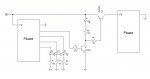
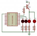
I need to control 3 LEDs (A,B,C for ease) which are required to be on or off at specific input pin states. A and B are straight forward as the PICAXE only needs to switch them on or off. C needs to be able to switch an LED and also connect to another PICAXE in replacement of a normal on/off switch. (In the circuit diagram below I've substituted the second PICAXE with another LED for ease.)

I'm using a 20M2 and have used PICAXE VSM to design the circuitry and all works as I want it.

However, I have read numerous things on the web and looked at so many circuit diagrams and one thing seems to be repeatedly shown, the 'switched component', whether it be a LED, relay coil or motor are all on the collector side of the transistor.

Is it possible to put an LED on the emitter side of things or is that a no-no at any cost?

Angie
test Sig Before.jpg
 

russbow

Senior Member
Not quite clear what you are trying to do.
Are you replacing D4 with a second picaxe input pin or the second picaxe +ve supply?

In either case your pin B.0 going high will surely give you what you need ?
 

AllyCat

Senior Member
Hi Angie,

Yes, your pictured circuit probably will work fine, it's called an "emitter follower" configuration and in many cases the 1k resitor is not even necessary. However, the base-emitter voltage drop will "lose" about 0.7 volt, so the top of the LED, etc. is unlikely to see more than about 4 volts. Probably not an issue in your case, but it could be if using a white or blue LED and three slightly flat AA cells in the power supply. So a PNP transistor (emitter to 5V) would normally be a better configuration.

However, russbow is correct, you can probably drive the LED/PICaxe directly from a PICaxe pin. But you really should show exactly how you intend to drive the second PICaxe, because there might be other issues with pull-up/down resistors and potential (fault) through-currents, etc..

Cheers, Alan.
 

Goeytex

Senior Member
I would suggest that your pictured circuit will not work very well, unless you are ok with only about 4.0 volts supplied to the second Picaxe (given a 5v supply). In the emitter follower configuration about .8 to .9 volts will be dropped across the transistor. This is why an emitter follower is almost never used for a high side switch. The preferred method is either a PNP transistor or P-FET. Below is how I might do it using a PNP transistor. The NPN transistor is to invert the signal so that a high signal from the Picaxe 1 turns on the PNP.
 

Attachments

Last edited:

SD70M

Senior Member
Thanks for the replies guys.

The second output of B.0 would be going to an input pin of a second PICAXE via a 1K resistor with a 10K resistor to ground, as if using a button press input.

@AllyCat and russbow
From what you have said this will work and is fine. Sorry if you misunderstood the second PICAXE connection, it's simply as a button press input. :)

@Goeytex: I understand what you mean if I was powering the second PICAXE from the pin but it's simply an easy form of communication, such as a button would do, so 4V or less would still work, which is what I had simulated and it worked.

I was just concerned as to why so many circuit diagrams have the load on the collector side of a transistor which, in my case, would not be possible using one transistor, which in turn would make the circuit larger and smaller is better in this case.

Hope this makes more sense.

Thanks again

Angie
 

inglewoodpete

Senior Member
As an aside, 120ohms is a bit on the small side for a current limiting resistor, unless the LEDs are white or blue. A typical red, green or yellow LED will drop about 1.8 to 2 volts, leaving about 3 volts to be dropped across the resistor. Using ohm's law, I = E / R = 3/120 = 25mA which is right on the limit of the PIC's capability. Personally, I would use a minimum of 220ohms: everything will be less stressed and last longer.
 

AllyCat

Senior Member
The second output of B.0 would be going to an input pin of a second PICAXE via a 1K resistor with a 10K resistor to ground, as if using a button press input.
Hi Angie,

So you don't need to use a transistor at all, direct drive from the PICaxe pin should be fine, and you can save some space.

But 120 ohms is indeed a little low for a PIXaxe to drive a red LED from a 5 volt supply, I'd use perhaps 180 ohms (or higher, depending how bright I wanted/needed it to be).

Cheers, Alan.
 

SD70M

Senior Member
@MFB
Sorry, I think my explanation was rubbish as you've misunderstood. I've added the required end result circuit below.

@IWP and AllyCat
Thanks guys, I used 120R resistors as I have a VERY large overall circuit (27 picaxes in specific places) and in VSM to view the whole layout I have to zoom out which makes seeing the led light up very difficult so I made them brighter by using a lower resistance :)

The actual resistors will be even higher than you say IWP as I've tried the 220R's and the LEDs are too bright by far. I'll be testing for correct brightness before final assembly.

@AllyCat
Is it possible to drive an LED and a Picaxe input pin, or for some, 2 or 3 inputs pins (as button press) directly? I didn't want to stress the Picaxe output by drawing too much current from one Picaxe output pin.

Again all, thanks for your time and input.

Angie
 

Attachments

Goeytex

Senior Member
Here's a little secret ... Given a 5 volt supply, a Picaxe cannot deliver 5 volts @ 20ma through a resistive load. Simply cannot do it.

When the current reaches about 15ma the voltage at the I/0 pin drops to about 4.0v. When the current reaches about 20ma the voltage will drop to about 3.2 volts. So keep this in mind when driving LED's at currents greater than 10ma directly from a Picaxe I/O pin.

I try to drive my LEDs at 10ma or less if driven directly from a Picaxe I/O.
 

AllyCat

Senior Member
Is it possible to drive an LED and a Picaxe input pin, or for some, 2 or 3 inputs pins (as button press) directly?
Hi Angie,

Yes, certainly. The loading of (even multiple) PICaxe inputs is negligible, it's really only the 10k pulldown resistor, and you only need one of those, even when driving multiple inputs. However, for safety, it might be wise to use an individual 1k in series with each input.

I've never actually measured the voltage on PICaxe pins at those currents, but Goeytex may well be correct, as the Microchip data sheet doesn't specify (characterise) the voltage drop at a pull-up current above 3.5 mA (a maximum drop of 0.7 volt). However, they do specify the voltage at a pull-down current of 8 mA (a maximum of 0.6 volt) so it's normally better to connect LEDs to the supply rail (and modify the pin-driving software to "active pull-down") if brightness is a particular requirement. But I certainly wouldn't rely on the outputs having a sufficiently high resistance to limit the current to any particular value (hence still using the 1k resitors above, in case any input gets accidentally switched as an output).

Also, in this particular case, I would NOT change to "active low" drive, because the input pin threshold (the nominal point at which it switches from detecting a '0' to a '1') is about 1.4 volts, i.e. not half-way between the rails.

Cheers, Alan.
 

SD70M

Senior Member
Thanks Guys,

I think I understand from both your comments that my circuit will work, as it does in the simulation.

Angie
 
Top