Switching ground with a P channel FET?

Shafto

Senior Member
I thought this was possible, but maybe not, I seem to have myself confused now.

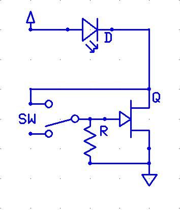
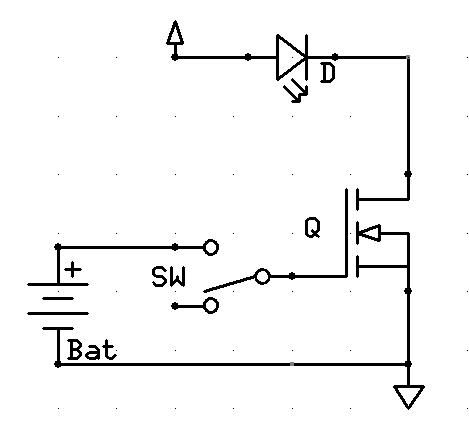
I want to use a mechanical switch to energize a FET into conducting the negative side of an LED to the battery ground.

I wired it so that the source is connected to -LED, drain connected to BAT GND, the gate with a 100K to the source, and the mechanical switch switches the gate to the drain.

I thought this was the right way to do it, but it doesn't work. Touching the gate with my finger, which I did by accident, works, but nothing else. Is this just not possible? A + source isn't physically available and the mechanical switch alone won't like the current.

Will a BJT work for this?

Thanks.
 

BeanieBots

Moderator
To pull a load down to ground (low side switching), you need an N type.
You CAN use a P type but you will need to pull the gate voltage BELOW 0v.
 

Shafto

Senior Member
I suppose that would be even better then, as the resistance of an N channel will be lower. I guess I had it in my head that since I only had the ground available I needed to use the ground to switch the FET, meaning a P channel.

To use an N channel I should just wire it like this?


Thanks.

Edit: Hmm, now that I look at it, doesn't seem like that will work either. Maybe this isn't possible with no access to the +V?
 
Last edited:

Shafto

Senior Member
I know this is a simple concept.. I just can't seem to quite wrap my head around how to do this with no +V.

..I have been thinking about it.
 

Dippy

Moderator
Haven't you got a +V on the high side of the LED?

An N chan MOSFET requires X volts applied at the Gate with-respect-to the Source.
Therefore if your source is 0V then the Gate must be fed X volts to make it conduct.
Hence the specs/graphs for Vgs.
 

Shafto

Senior Member
Yes there is a +V but it's not physically accessible as I mentioned in the first post.

I suppose I was thinking that the source would be more positive than the drain, and it is.. it conducts very slightly, due to the resistance in the FET, but, obviously not enough voltage to work properly.

I haven't played around with FETs that much, it's just now that I realize P channel switches high side and N switches low (without extra circuitry). I thought either was usable, and you just applied GND to a P to make it conduct, and +V to an N, Which is why I tried to use a P channel, as I had the GND available.

I see the err of my ways now. I guess the only way to make this work would be to utilize a small watch battery in the switch? Or am I dreaming again, is it ok to use a separate source to drive the gate? Looking at some datasheets gate to source leakage current is around 100nA, so the battery would last forever.. if it would work.

Would a diode be necessary between the small battery and the gate?

Thinking something like this:


Edit: Hmm.. the arrow in the symbol switched the other way when I chose the "enhancement" FET.
 
Last edited:

Dippy

Moderator
"I thought either was usable, and you just applied GND to a P to make it conduct, and +V to an N,"

- No, not quite. Maybe a bit of a reading-up is due?

Then when you read Data Sheets it becomes clearer.

You will see a spec and graphs for Vgs.

Vgs = Voltage at Gate With respect to Source.

You will see for P Chans it is a MINUS figure wrt source. Therefore you should understand Beaniebots comment above.

Your battery idea should work in principle, but AGAIN look at the Data Sheet.
What voltage will you require at the gate to get the MOSFET to switch on fully?

Why do you want a diode? Some kind of protection?
I would be tempted to add a 10K - 47K resistor (batt to switch) to save any accidents/embarrassment.
Also a resistor (big value e.g. 1MOhm) from Gate to ground - otherwise with the Gate capacitance it may stay on for yonks after switching off.


And, I am bursting to ask, if it's just an LED what is wrong with a tiddly toggle? Some have pretty healthy ratings.

Anyway, off to work now. BB and others can help you better than me. Good luck :)
 

Shafto

Senior Member
Yes, I see now the Vgs and how everything relates. Thanks!

I did look at the graphs before, and chose a P-channel that was optimized for the low voltage I'm using, so I did go over all of that, but, my logic how it worked was flawed. I figured the GND would be -3.7V from the Power supply.

The diode I was figuring, to stop any kind of feeding between batteries, the primary supply and the small watch battery for the FET, but I suppose it's not needed.

Why would you be tempted to add a resistor between the switch and the small battery?

The FET is needed because I'm using almost 6A of current... at 94 lumen/W, it's some pretty serious illumination :)

Are the gate to source leakage current and the battery self discharge the only drains on the battery? That's almost too good to be true. A small 3V lithium watch battery should last for 5 years.


Thanks a lot for the help! You guys always set me straight with my limited electronic knowledge. Always saves me on my LED projects.
 

Dippy

Moderator
The resistor to do protection in the event of a wiring cock-up or some wierd failure of MOSFET.

A 3V lithium? Will your MOSFET be 'fully ON' with a Vgs of ~3V (which may droop with time)??
Time to visit those Data Sheets again methinks.

Done any power calcs for your chosen MOSFET?
You haven't specified a device here so none of the rest of us can do it for you.

If your MOSFET isn't at it's minimum Rds then you may be able to use it for cooking some suasages.
 

Shafto

Senior Member
Well, after figuring out that I need an N channel, I've been looking.

There are FETs designed to work from that low voltage, they are made for use in Li-Ion battery protection circuits.

I was thinking this one looked good, the lowest resitance without the need for a high gate voltage at a decent price, that I could find so far.

http://www.infineon.com/dgdl/BSC026N02KS+G+Rev1.05.pdf?folderId=db3a3043163797a6011637c252b10018&fileId=db3a3043163797a6011637c2a4280019

I'll look through some more datasheets tomorrow, time for bed!
 

BeanieBots

Moderator
No PICAXE in this then?
If there was, of course it would supply the required drive (for a logic level FET) to enable the FET to come on.

As Dippy mentions, how hard will your chosen FET be driven with Vgs = 3v?
Also as advised, fit a series resistor for safety.
 

InvaderZim

Senior Member
If you are using a switch anyway, I'd just get one rated for the job. It's easy to find 6A or even 10A switches that aren't very large, especially for low voltage apps. In a pinch use the ones you can buy for $0.50 for extension cords. FETs like to blow up if you aren't extra careful, if not immediately then for seemingly no good reason a month from now.
 

MPep

Senior Member
Don't forget to insert a resistor in series with the LED also. Otherwise you'll stress the LED until it goes "POP".:eek:
 

McTaggart

New Member
Unless you use a switch with gold contacts don't expect any arrangement with so little current to work for very long. Normal switches need current to clean the contacts (~15/20mA is commonly used.)
 

Shafto

Senior Member
How does a watch work then? They don't use gold plates contacts. I'm sure tin is just fine.

Thanks for the help, everything works just as I had hoped. Switch is to send current to the LED driver, that stops the LED from going "POP".
 

BeanieBots

Moderator
McTaggart is actually correct that switch contacts also have a minimum current rating as well as the more obvious maximum one. However, in reality, you only need to worry about if you are in the space or medical industry.
For very high reliability at very low currents, use "murcury wetted" contacts.
 
Top