Switch Input problem with 14M

charcoal

New Member
I know that there is probably a stupidly simply solution to this, but for the life of me I can't see it.

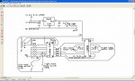
Building simple robots in class room situation, using the 14M to drive the things, a L293D is driving two motors, a couple of micro switches on the front to detect when it runs into a wall etc. The input pins of the 14M are all tied low via 10k resistors (one resistor per input). Two of the inputs are connected to the micro switches and go high when the switches close.

Can write a simple program to switch on the motors on and get the robots moving, but when I add in the code to see if the switches have gone high (when the bot runs into something) then the motors stop and begin to 'hunt' (ie perform a very small incremental shuffle back and forth).

Have played with the software, which runs OK in the simulation, the best I've managed to do is to get the motors to stop completely. Am using an IF...THEN statement to do this, eg. IF pin2 = 1 THEN motorstop

Checked pins with logic probe for highs and lows, everything seems OK

Suspected hardware issue and built the circuit (used new set of components) up on a prototype board, have exactly the same problems.

Talk about frustations, if I had hair I'd be pulling it out.

Any suggetions?
 

Billo

Senior Member
It might be an idea to post your code. You'll learn more from someone pointing out where you went wrong rather than someone just writing the code for you.
 

westaust55

Moderator
Also please post your project Schematic diagram to help folks here understand your project.
That way, even simple things like the code "looking" at the right pin can be checked.
Clear photos of the circuit boards (top and bottom) enabling folks to trace the circuit can also be useful.
 
Last edited:

Paix

Senior Member
@Gumtree, the circuit diagram would be helpful also, to tie in with your code in case there are any mismatched instructions and port pins. It's always easier with the full picture.

It should also become a good habit to present your questions with comprehensive documentary support. It impresses the hell out of the regular guru's that spend hours polishing their crystal balls trying to figure out the permutations when the assumptions differ from reality.
 

charcoal

New Member
Righto guys, got the message, will get schematic and code posted asap though it may not happen till tomorrow.

regards
 

charcoal

New Member
Circuit schematic and program listing for simple robot

Hi guys,

in reply to the request for the schematic and program listing, hopefully I've done the right thing and managed to get the files attached. The program listing has been done in the Picaxe Program Editor, and is pretty simple at this point as it was only intended to prove that the hardware worked. Students were then supposed to build on this and create their own program to drive the robot. The program, at the moment is just to drive the bot forward till it hits an object, stop, back up, then go forward again.

The schematic diagram is in a word doc. There is not switch debounce components shown, we've tried the circuit with and without these with no difference in the way it behaves.

Have discovered a new behaviour with the circuit I built up on the proto board. When initially powered on only one motor will start up. Briefly disconnecting the non running motor then reconnecting it causes it to start. This breadboard version is powered from a bench top supply, so it's not an issued of voltage or current.

Would be grateful for any suggestions

regards
 

Attachments

lewisg

Senior Member
The most obvious problem I see in your code is RHturn: and LHturn: do the same thing.

My guess is the "hunting" might be due to the tight hit: loop.

For chuckles try this:
Code:
#picaxe14m

symbol HitL = 0                 'left hit switch
symbol HitR = 1
symbol Lfor = 2                 'left motor forward
symbol Lrev = 3
symbol Rfor = 5
symbol Rrev = 4


main:
    high Lfor                   'lets go!
    high Rfor                   'lets go!
    if HitR = 1 then RHback     'right side obstruction, pivot left
    if HitL = 1 then LHback     'left side obstruction, pivot right
    pause 250
goto main

RHback:
    low Lfor                    'turn off LHM
    low Rfor                    'turn off RHM
    pause 100                   'wait 0.1 seconds
    high Lrev                   'turn on LHM in reverse
    pause 125
    low Lrev
    low Rrev
 goto main

LHback:
    low Lfor
    low Rfor
    pause 100
    high Rrev                   'turn on RHM in reverse
    pause 125
    low Lrev
    low Rrev
goto main
symbols keep you sane...
 

westaust55

Moderator
I cannot immediately see anything wrong with the code relative to the schematic diagram. In re-reading the line:
Can write a simple program to switch on the motors on and get the robots moving,
but when I add in the code to see if the switches have gone high (when the bot runs into something) then the motors stop and begin to 'hunt' (ie perform a very small incremental shuffle back and forth).
This suggests that one or both of the inputs are being seen as high either continuously or frequently.
Your test code as written for the two blocks RHturn: and LHturn: are identical so the motors run in forward then if an input is high the motors stop, reverse for 0.125 secs, stop and go back to the start which explains the "shuffling back and forth" that you mention.

Questions:
1. Are you definitely using an 14M and not a 14M2?
2. Does the “shuffle” occur when the switches are not activated or are you testing against a wall?
3. Are you sure the input bump switch contacts are wired as normally open?
4. What happens if you have the inputs connected but no outputs connected?
 

eclectic

Moderator
Posted to save time opening other programs.

Code:
main:
high 2 'turn on LHM
high 5 'turn on RHM
hit:
if pin1 = 1 then RHturn 'detect hit object hit 
if pin0 = 1 then LHturn 'detect hit object hit
goto hit
RHturn:
low 2  'turn off LHM
low 5  'turn off RHM
pause 100 'wait 0.1 seconds
high 3 'turn on LHM in reverse
high 4 'turn on RHM in reverse
pause 125 'wait 0.125 seconds
low 3  'turn off LHM
low 4  'turn off RHM
pause 250 'wait 0.25 seconds
goto main
LHturn:
low 2  'turn off LHM
low 5  'turn off RHM
pause 100 'wait 0.1 seconds
high 3 'turn on LHM in reverse
high 4 'turn on RHM in reverse
pause 125 'wait 0.125 seconds
low 3  'turn off LHM
low 4  'turn off RHM
pause 250 'wait 0.25 seconds
goto main
 

Attachments

charcoal

New Member
I should add to my previous reply concerning the comment by westauz55 that perhaps you misinterpreted my description of the 'shuffle' efffect. It is ongoing, which is not what the code is instructing the pic to do. The motors should stop briefly, then it should do a short back up (and the switch will turn off as it backs away from the obstacle, currently we are just taking our hand out of the way) and then the code should go back to the main program which starts the motors going forward again.

We are not even seeing the brief pauses that are suppose to be happening, the switch is breifly tapped to provide an ON-OFF pulse and the motors go immeadiately into this 'shuffle'. On my breadboard hookup, the motors stop briefly and then continue on forwards.
 
Top