Hi there
Just a quick nuance and may be some light shed on suppression from DC motors ( small eccentric motor type=
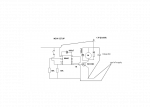
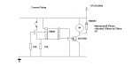
Operating from a battery supply, 08M2 chip and using BCX38C, 4001 diode protection( although would love to know if the1N5819) Schottky Diode would be more suitable?
using PWM for driving the motor and later switching to Haptic Drives using H Bridge driver chip. Although have had the problem using PIN high to drive motor through BCX38C
Ok, so we can place a Suppression Cap ( polyester 220nf across motor)
A few questions..isolated a few obvious problems and curiosities before I post that could be the answer..or contribute to a better working more reliable and protected circuit-
The obvious been the cap missing across the motor. But there seems to be no pics of a cap across the Chip rails, although its mentioned, should this only be used with regulated power supplies and not needed with batteries. .?
All good and well,, But .
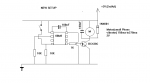
1)Do we need to have protection across the rails running from a battery supply? its not shown( or I have missed it) in the manual 3 interfacing .? (Not got any, what would you suggest?)
2)does or should the base/gate of BCX38C be tied to ground with a 10K resistor like a Mosfet would? ( any technical expert can step in here, just curious)
3) is the 1K critical between output pin and base of BCX38C? ( I have not included it, due to this device not needing it with another microcontroller and worked fine)?
The Reason I ask this, is because if I use simple HIGH commands to drive DC motor for short bursts, not often(weeks without), but sometimes, the motor will just flip into constant running until I cut the power..
4) I did not have suppression cap protection across the motor..
I will include a schematic hopefully tonight as i know a pic tells a thousand words.
Regards
Tesla
Just a quick nuance and may be some light shed on suppression from DC motors ( small eccentric motor type=
Operating from a battery supply, 08M2 chip and using BCX38C, 4001 diode protection( although would love to know if the1N5819) Schottky Diode would be more suitable?
using PWM for driving the motor and later switching to Haptic Drives using H Bridge driver chip. Although have had the problem using PIN high to drive motor through BCX38C
Ok, so we can place a Suppression Cap ( polyester 220nf across motor)
A few questions..isolated a few obvious problems and curiosities before I post that could be the answer..or contribute to a better working more reliable and protected circuit-
The obvious been the cap missing across the motor. But there seems to be no pics of a cap across the Chip rails, although its mentioned, should this only be used with regulated power supplies and not needed with batteries. .?
All good and well,, But .
1)Do we need to have protection across the rails running from a battery supply? its not shown( or I have missed it) in the manual 3 interfacing .? (Not got any, what would you suggest?)
2)does or should the base/gate of BCX38C be tied to ground with a 10K resistor like a Mosfet would? ( any technical expert can step in here, just curious)
3) is the 1K critical between output pin and base of BCX38C? ( I have not included it, due to this device not needing it with another microcontroller and worked fine)?
The Reason I ask this, is because if I use simple HIGH commands to drive DC motor for short bursts, not often(weeks without), but sometimes, the motor will just flip into constant running until I cut the power..
4) I did not have suppression cap protection across the motor..
I will include a schematic hopefully tonight as i know a pic tells a thousand words.
Regards
Tesla
Last edited:
")