Strange 18M2 malfunction

saunj

Senior Member
I have a complex project which worked Ok until I put C.0 low (it connects to a SSR) Then it went haywire. C.0 was being held high
not by itself, but internally, and it took about 30 MA to bring it down. After checking the circuit, I switched to a spare chip, and that fixed the
problem. I discovered a 5 us neg pulse on C.0 at the 1 sec period of the DS1307 square wave which paces this device. This pulse I
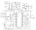
think is the same as one on B.2. The bad 18M2 works OK in a bare breadboard, so maybe it cannot tolerate some of the items in the actual circuit, which include:
2 ADC inputs, two pins with pulsout, I2C and continuous PWM.
 

BeanieBots

Moderator
Without a full circuit diagram we can only guess.
You mention a SSR. Are you switching mains?
If yes, what precautions have you taken about EMC, RFI and other volt spikes?
What is the load? Very inductive? Got any snubbers fitted?
Have you properly decoupled the PICAXE?
What is your power source? Is it coupled to the load?
 

Dippy

Moderator
In addition to BB's list of questions and assuming you don't have a duff chip...


Most failings like this are down to inappropriate design, components, loadings, power or layout of the circuit.
You mention a 5uS neg pulse... where is this coming from, what is the amplitude?
Are you simply seeing a the reactive pulse you sometimes get with SS switching? (Or have you left your scope on AC coupled?).

Are you driving 30mA direct from PICAXE o/p ?


Your 'fix' may be just luck and the rest of the circuit is waiting to kill it tomorrow.
Your device may be living on the edge of a cliff :)


If you want some assistance you should post your actual schematic, any photos and links to special components (e.g. SSR).
 

hippy

Ex-Staff (retired)
I discovered a 5 us neg pulse on C.0 at the 1 sec period of the DS1307 square wave which paces this device. This pulse I think is the same as one on B.2. The bad 18M2 works OK in a bare breadboard
It sounds like there may be some sort of short on your board. Post a circuit diagram and perhaps photos of what you have.
 

nick12ab

Senior Member
You do have decoupling capacitors fitted, right?

Have you checked the code carefully to see if there is an error that will set the pin high under certain conditions? Check for any typos and particularly any missing decimal points in high commands since it can cause the command to use the value of a variable to determine which pin to set high e.g. high b7 instead of high b.7.
 

saunj

Senior Member
You asked for details .... Here they are

Without a full circuit diagram we can only guess.
You mention a SSR. Are you switching mains?
If yes, what precautions have you taken about EMC, RFI and other volt spikes?
What is the load? Very inductive? Got any snubbers fitted?
Have you properly decoupled the PICAXE?
What is your power source? Is it coupled to the load?
The SSR can take care of itself - it was previously used to control a tube-type computer monitor and is probably opto-isolated. It draws about 3 MA
The load so for is an incandescent lamp, no precautions are needed, the SSR is a quality Teledyne, rated 5A at 115VAC.
The chassis is grounded, the circuit floats with a high-volt capacitor and 1.5 M to ground.
Of course it would be grounded in testing to the programming PC and the Tek DSS.
The device is powered by a switching "Wall-wart" regulated at 5.3V, 1A. In addition to its capacitor there is a 470 uF and a 100nF on the board.
I was using there same line.
As for other inquiries:
I checked for all conceivable shorts with an ohmmeter before I gave up and put in a spare 18M2. That has been going for a day with no problems
in the same circuit and software. When I saw the pulse, the C.0 line was in input state. The pulse appears to be the same as the one from B.2,
but I couldn't check because the 18M2 is hidden under a ribbon cable. The pulse was well-formed, negative going and varies with clock frequency.
A high on C.0 slightly increases the voltage on C.0, and does not cause the display to go bad. With C.0 as an input its voltage decreased to 2.4V
with a 150 ohm to common.
Testing the removed 18M2 on a bare breadboard with a test program shows no coupling between C.0 and any other output pin.
Here are the program for the display processor (There is a 14M2 for IR) and the relevant circuit part:

View attachment AlphaLEDClockDisp4.basDisplayProcessor.jpg
 

BeanieBots

Moderator
Symptoms are typical of an OPEN circuit on a ground line. (current flows through I/O pins instead of ground/Vcc)
Switching incandescent lamps can generate HUGE start currents when the lamp is cold.
Depending on EXACT wiring layout, this could easily get into the PICAXE circuitry.
A photo of layout would help.
 

saunj

Senior Member
Symptoms are typical of an OPEN circuit on a ground line. (current flows through I/O pins instead of ground/Vcc)
Switching incandescent lamps can generate HUGE start currents when the lamp is cold.
Depending on EXACT wiring layout, this could easily get into the PICAXE circuitry.
A photo of layout would help.
Can't be - its working fine for many hours now with a spare 18M2. Besides it had the high problem with no load. Ground has 2 pins
I was planning to test in a breadboard with the same program. I got as far as making and testing a DS1307 RTC module when I
fell down our back steps, hit my right knee on a brick planter and tore its tendon.
It will be months before I can continue this. TTFN
 
Top