stereo jack to breadboard

fran1942

New Member
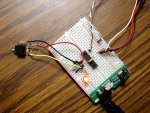
Hello, I am going to set up a picaxe circuit on a breadboard including a stereo jack for computer interface.
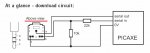
I see you can buy pre-made Picaxe breadboard Programming adaptors that include the stereo jack and they also have a jumper arrangement to alternate between programming download and output.
Than again, I have also see guys just wire up their own stereo jacks direct to the picaxe pins on the breadboard. They dont seem to have this jumper arrangement to alternate between download and output mode.

My question is, is this jumper necessary or can I just leave it out on my breadboard.

Thanks for any help.
 

cravenhaven

Senior Member
I dont know what the breadboard jumpers are for, but if you plan on using i/o routines such as SERTXD/SERRXD then all you need is the jack wired directly to the picaxe as per manual 1. This gives you the ability to program the device whilst in circuit and communicate with your program.
 

boriz

Senior Member
"is this jumper necessary..." No.

"can I just leave it out on my breadboard..." Yes.

There are exceptions, but generally, don't worry about it.
 

fran1942

New Member
thanks guys for the help.
I went and bought a 3.5mm stereo jack socket, but I am unsure which pins I should use (pic attached).
I understand that one pin should connect to ground, one pin to pin 7 of the Picaxe and one to pin 2 of the Picaxe.
That is three connections however this stereo jack socket has 5 pins. Can someone please tell me which of these socket pins are the correct ones to use.
Then, what do I do with the 2 excess pins, do I just bend them over so this socket can sit flush on a breadboard. (I guess I will have to solder pins onto the legs of this socket so it can fit onto the breadboard).
Sorry, but I am an electronics newbie trying to learn all of this stuff.

Thanks kindly for any help.View attachment 8666socket.jpg
 

fran1942

New Member
thanks guys for the help.
I went and bought a 3.5mm stereo jack socket, but I am unsure which pins I should use (pic attached).
I understand that one pin should connect to ground, one pin to pin 7 of the Picaxe and one to pin 2 of the Picaxe.
That is three connections however this stereo jack socket has 5 pins. Can someone please tell me which of these socket pins are the correct ones to use.
Then, what do I do with the 2 excess pins, do I just bend them over so this socket can sit flush on a breadboard. (I guess I will have to solder pins onto the legs of this socket so it can fit onto the breadboard).
Sorry, but I am an electronics newbie trying to learn all of this stuff.

Thanks kindly for any help.View attachment 8666
 

srnet

Senior Member
To be sure you have the right connections, since jack sockets do vary in layout, check with a multimeter\buzzer which pins on your socket are actually connected to the tip, ring and body of the jack when its plugged in.
 

hippy

Ex-Staff (retired)
Then, what do I do with the 2 excess pins, do I just bend them over so this socket can sit flush on a breadboard. (I guess I will have to solder pins onto the legs of this socket so it can fit onto the breadboard).
Jack sockets aren't designed for fitting to breadboards so can give poor contact when they are, leading to all sort of download issues. The easiest thing is to add flying leads from the pins ... or to use the breadboard adapter
 

westaust55

Moderator
Download manual 1 for the pixaxe. The wiring is shown on page 45
And if needing to test the socket for compatability then also see the diagrams in PICAXE manual 1 (V7.7) on page 44.


I think there is some confusion over jumpers between the jumper on some Rev Ed boards for "M" parts where output 0 i shared with the SerialOut pin for programming and SERTXD purposes.

Believe MicroZED in Australia sell the AXE029.
For breadboard use, it is an easy way to go.
It would be easy enough to construct your own version if you wish.


Rev Ed also have the AXE029 breadbaord adapter. http://www.rev-ed.co.uk/docs/axe029.pdf
With the AXE029, there is a jumper that is primarily for allowing the suer the match the SerialIn, SerialOut and 0V pins for the (a) 18 pin parts, and (b) for the 28/40 pin parts.
 

inglewoodpete

Senior Member
An alternative that I use is this minimum operating circuit which I posted several years ago. It allows a PICAXE to be programmed and run in-and-out of a circuit. The whole assembly can be plugged into a breadboard or a PICAXE socket on a PCB. The concept can be adapted and used with any model PICAXE.
 

KMoffett

Senior Member
You can get panel\chassis mount versions of course, a lot easier to attach wires to.
A problem with the chassis/panel mounted programming jacks is that most of these jacks are designed with the intent of the threaded barrel being grounded to the chassis/panel. With the way the manual has the connections arranged, serial-out from the PICAXE would then be connected to the barrel and thus grounded to the chassis. :( 
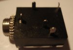
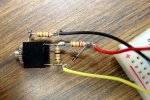
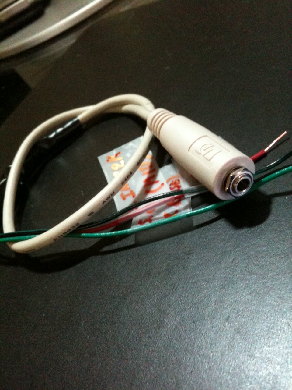
You can buy insulated jacks, or use shoulder and insulated flat washers to insulate the barrel. I decided to rearrange the connections so PICAXE common goes to jack barrel and chassis ground: http://www.picaxeforum.co.uk/showthread.php?18512-Download-cable-plug-wiring...why&p=175373&viewfull=1#post175373

It can also take care of the serial-out/operate jumper automatically.

This is now my standard....and I'm sticking to it. ;)

Ken
 

srnet

Senior Member
A problem with the chassis/panel mounted programming jacks is that most of these jacks are designed with the intent of the threaded barrel being grounded to the chassis/panel.
True, but then the panel on the end of my breadboard is plastic ......
 

Goeytex

Senior Member
Personally, I don't care too much for the stereo connector, especially on a breadboard. IMO a stereo plug is not the most reliable of connections.

I soldered 3 inch leads on a stereo jack and then put a 3 pin IDC connector on the other end. This makes an adapter. Then put a 3 pin header on the breadboard for programming/debug. Works fine and takes up less space.on the breadboard.
 

KMoffett

Senior Member
True, but then the panel on the end of my breadboard is plastic ......
My change in the plug/socket configuration was not because of the breadboard. I had previously used a 3-pin header plug to the breadboard. It was because most of my projects wind up in metal enclosures. I wanted to be able to reprogram without opening the case. Insulating the jack's barrel for the serial-out contact was an inconvenience. But, in making the change, it turned out to be an automatic way to also switch the serial-out from operate to program and back to operate with just the programming plug...no more header-jumper swapping.

Ken
 
i HAVE RECENTLY BREADBOARDED A picaxe CHIP.

I used the 3.5mm stereo jack supplied by technologysupplies. I found that the manual part 1 illustrates the stereo jack as viewed from above, but it is viewing the bottom of the jack with the pins pointing up towards you. Looking as the jack as it is inserted in the breadboard with the entrance for the plug away from you ground pin is the the left - it worked for me ! I don't think this is very clear in the manual. I soldered stiff wires onto the pins (which are really too short [the pins that is] to hold on to a breadboard reliably) and used then as pin extensions not a particularly good solution I admit. A far better solution in my mind (now that I've discovered it) is the AXE025 cable with 3 pin header also available from www.technologysupplies.co.uk (discontinued ???). (I bought a small board for another purpose with such headers as contacts and this plugs into my breadbaord, but I don't know if that's good practice or not).

I lso thought of mounting the jack socket onto a small bit of vero board wich would also hold a single in line header three pins wide algned with the three pns on the socket.

Maybe I'm going to supply to power to my breadboad in a similar fashion.

AB
31.July.2011
 

IronJungle

Senior Member
Tracecom:

Your method is exactly what I was going to do. However, aren't the 10K and 22K needed for the PICAXE (18M2) to function? If I understand your circuit, these two Rs will be removed when you pull the programming plug off the breadboard.

Comments?
 

nick12ab

Senior Member
Your method is exactly what I was going to do. However, aren't the 10K and 22K needed for the PICAXE (18M2) to function? If I understand your circuit, these two Rs will be removed when you pull the programming plug off the breadboard.
I use that breadboard adaptor and when using multiple PICAXEs, I add a 10k resistor to each PICAXE so the PICAXE with the programming adaptor therefore has two 10k resistors in parallel. The PICAXEs without the programming adaptor still work fine and the PICAXE with the programming adaptor still downloads. If you're using the AXE027 PICAXE Download cable, a higher value may be required since that uses 5v signals instead of the 10v signals that are provided by the AXE026 PICAXE download cable.
 

westaust55

Moderator
I found that the manual part 1 illustrates the stereo jack as viewed from above, but it is viewing the bottom of the jack with the pins pointing up towards you.
The view of the 3.5mm Stereo socket could (by drafting parlance) be considered as a sectional top view.
So the SerialIn pin is at the bottom rear right (if that is plain enough) as orientated/viewed form the top.
 

Attachments

westaust55

Moderator
Tracecom:

Your method is exactly what I was going to do. However, aren't the 10K and 22K needed for the PICAXE (18M2) to function? If I understand your circuit, these two Rs will be removed when you pull the programming plug off the breadboard.

Comments?
Welcome to the PICAXE forum IronJungle.

IMHO if one is using a breadboard, the entire circuit is a prototype and temporary. I often use an AXE029 equivalent and do not remove the programming socket from the circuit.

You are correct in that the SerialIn pin MUST be held in a low state (best done with a pull down resistor as Nick12ab indicates) if the socket and resistors are in fact going to be removed.
The alternative/option available with most PICAXE chips is to use the DISCONNECT command which is necessary if you wish to use the SerialIn pin for other input purposes when a program is running.
 
Last edited:

nick12ab

Senior Member
The alternative/option available with most PICAXE chips is to use the DISCONENCT command which is necessary if you wish to use the SerialIn pin for other input purposes when a program is running.
But you mustn't use that to save on a resistor as if it's floating in the high state on startup, the PICAXE will appear to be non-functional for a few seconds since it checks for a download before the first command in your program.
 

westaust55

Moderator
Yes, I have never used the DISCONNECT command personnally and had that thought in the back of my mind shortly after hitting the post button
 

tracecom

Senior Member
Tracecom:

Your method is exactly what I was going to do. However, aren't the 10K and 22K needed for the PICAXE (18M2) to function? If I understand your circuit, these two Rs will be removed when you pull the programming plug off the breadboard.

Comments?
You are correct, but as others have posted, I use this arrangement for breadboarding and consider it temporary. A more permanent circuit would need to have the resistors permanently installed.
 

IronJungle

Senior Member
OK, I found this from an old HP computer (see pic). I can plug it into a breadboard or alligator clip it to a PCB. Works fine. Thanks again.
 
I have a 40X2 which I plan to use on a breadboard. I obviously need to to be able to download my programs onto this chip, but the pinout of this chip does not seem to compatible with the AXE029 (0V pin is not adjacent or adjacent-but-one to either SEROUT or SERIN), only with what are described as 'older' chips in the PICAXE manual I. Can anybody confirm this ?

Has anybody thought up a better way than to use AXE029 or (home-made board with socket attached) and connect the earth (0V) to 0V on the chip with a flying lead ? (or possibly set pin 8 or 9 output to 0V [logic 'low']) ?

Absolute_Beginner
19.October.2011
 

hippy

Ex-Staff (retired)
I use that breadboard adaptor and when using multiple PICAXEs, I add a 10k resistor to each PICAXE so the PICAXE with the programming adaptor therefore has two 10k resistors in parallel.
I missed this earlier and may be misunderstanding the context and actual circuit used, but if using a breadboard adapter and a 10K from Serial In to 0V then the two 10K will not be in parallel.

What one ends up with is a pi-shaped resistor network with the 22K and 10K forming a potential divider at teh PICAXE side. This may work in some circumstances but not in all.
 

hippy

Ex-Staff (retired)
I have a 40X2 which I plan to use on a breadboard ... but the pinout of this chip does not seem to compatible with the AXE029 (0V pin is not adjacent or adjacent-but-one to either SEROUT or SERIN)
Welcome to the PICAXE forum.

You are correct that the breadboard adapter is most suitable for use with other PICAXE as the pinouts on the 40-pin parts are different to what the AXE029 expects. The easiest solution is to insert the breadboard adapter further along the breadboard and connect the three pins to the PICAXE chip using flying wire.
 

westaust55

Moderator
@hippy,
It might be worth altering the AXE029 datasheet to flag that the direct options are for 18 pin and 28 pin chips (not 28/40 pin at one jumper setting).
Then as you suggest add a note to the effect that the adapter can be used with other chips by placing to the side and using jumper wires.
 

hippy

Ex-Staff (retired)
It might be worth altering the AXE029 datasheet to flag that the direct options are for 18 pin and 28 pin chips (not 28/40 pin at one jumper setting).
I'll make a note to consider some clarification.

I suspect that the thinking for 40-pin parts was that the jumper sets the pin order most appropriately so if used on a double-width breadboard it can be inserted then wires jumpered across without wires crossing over, even though it doesn't suit 'up against the PICAXE pins' use.

I'm so used to fitting connectors and adapters and then wiring to where the connections are needed that it's easy to forget others may be doing things differently!
 
OK, people, a simple question.

I have come across a new problem to me. I am thinking of making making my own interface board to carry the stereo jack. The issue is I am thinking of using a piece of one-sided stripboard and a male type pin header with an insulting piece joing the pins together asymetrically placed along the length of each pin, as is common; how do I (does one) solder the two together ?

Inserting the header into the stripboard by the 'short' of the pins from the copper track side s.t. they protrude through to the un-coppered side leaves only the mechanism of heating the pin from un-coppered side sufficiently to melt the solder s.t. it runs down though the hole and soldifies on the (cold) track underneath - this does not sound like a very reliable procedure to me, as in the process of soldering one is normally advised to heat both of the pieces to be joined and then apply solder. Do I need double-sided stripboard/pcb or even through-hole plated ?

Aside from the potential problems of melting the insulating stop on the header, I probably do not have powerful enough iron. This is a general problem with making boards for mounting on breadboards, so I am confident many of you out there will be able to advise, even if it's not what I want to hear !

Absolute_Beginner
23.October.2011
 

hippy

Ex-Staff (retired)
If I've got it right ... You have the jack socket on the top of the board, copper tracks underneath, and then need the header pins to protrude downwards, which means soldering underneath.

If so, the usual trick is to push the insulating plastic which joins the pins right to the ends of the pins, then insert from the top of the board so it's as you'd want. Then solder underneath.

Added : Random image from Google to show what I mean ...

http://openenergymonitor.org/emon/sites/default/files/B04.JPG

The insulating plastic can be moved to the ends by a number of methods, three of which I've used -

Holding the header loosely in a vice, so the plastic sits over the jaws, the pins dangle between the jaws, push or lightly hammer the pins down. Push with something metal, not your fingers!

Stand the header on a solid surface and push the plastic down with long nose pliers or a screwdriver between the pins. Don't do this on a desk, table or anything important as it will leave indentations.

Hold the header with long nose pliers so one leg is between two pins and the other leg touches the end of the pin, then squeeze.
 
Last edited:
Thank Hippy, I didn't realise the insulation on a pin header could be moved along the pins so "easily". That's the trick.

Your picture from google shows one way of solving it, but in fact I had in mind keeping the insulating layer on the conductor side of the board, as kind-of shown in the image here http://www.ebay.co.uk/itm/MMA7361-Accelerometer-Sensor-Module-AVR-ARM-MCU-PIC-/200608863688?pt=LH_DefaultDomain_0&hash=item2eb53855c8, where the contact must be on the top side of the (double sided) PCB.

Either way, the solution is being able to move the insulation.

Absolute_Beginner
23.October.2011
 

hippy

Ex-Staff (retired)
had in mind keeping the insulating layer on the conductor side of the board, as kind-of shown in the image here http://www.ebay.co.uk/itm/MMA7361-Accelerometer-Sensor-Module-AVR-ARM-MCU-PIC-/200608863688?pt=LH_DefaultDomain_0&hash=item2eb53855c8, where the contact must be on the top side of the (double sided) PCB.
Be careful with that approach. It works for double-sided PCB but doesn't work so well for strip-board.

I built a strip-board circuit for the AXE401 Shield Base that way, pins underneath, soldered underneath, plastic underneath, pins flush to the top of board. It looked nice, but very quickly the copper track got ripped away from the board. Had to throw it away and start again, wasting time, effort and money but I learned a valuable lesson ( "don't do it" ). The force when removing from breadboard will be far greater than from the header sockets on the AXE401.
 

MartinM57

Moderator
I just use the spare bits of resistor leads after they've been cut off after soldering - cut to 8-10mm and solder them vertically to the socket pins so that they go into the breadboard on the same centres as the original pins
 
Top