AS some of you know i have been working on a little project involving a stepper motor. I have made a bit of theortical progress but life is stopping me buy stuff for thing like the motor and ahaing a custom threaded bar cut.
but back to the theory and design, i have been looking at micro step controllers using something like the TB6560 or TH6064 when at work and with a little inspiration from stpperworld and idea hit me like a freight train.
why not have the wave patern pre-programmed into a picaxe. then i realised my analogue electronic isnt so hot
circuit so far
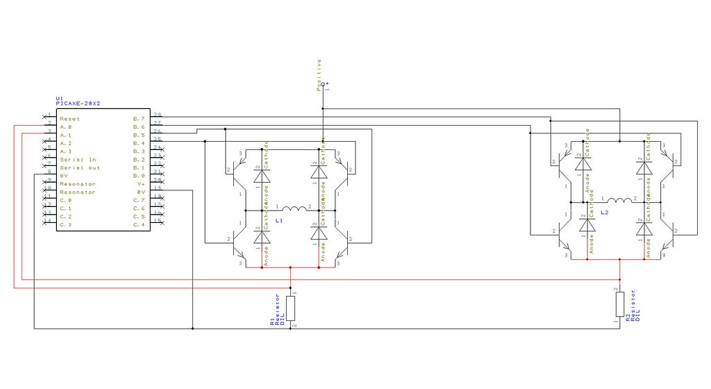
Driver 0.1 by f2268d215cc925918731918f4efa0289, on Flickr
now as you can there is no comparitor (should go on the red wires, one for each phase of the motor), this is the problem as it will be needed to stop putting too much voltage into the picaxe if you use a higher voltage motor, or you will loose resolution fro lower voltage. any ideas on the best type of circuit i should use, i know it will most likely by op-amp with some hysterisis but it will need to keep within 0-5v and follow the voltage arc from the phase of the motor
it a very rough start any ideas or testing or error i have made feel free to say something. the biggest thing is, will it work, and if so how well
http://www.stepperworld.com/Tutorials/pgMicrostepping.htm
but back to the theory and design, i have been looking at micro step controllers using something like the TB6560 or TH6064 when at work and with a little inspiration from stpperworld and idea hit me like a freight train.
why not have the wave patern pre-programmed into a picaxe. then i realised my analogue electronic isnt so hot
circuit so far
Driver 0.1 by f2268d215cc925918731918f4efa0289, on Flickr
now as you can there is no comparitor (should go on the red wires, one for each phase of the motor), this is the problem as it will be needed to stop putting too much voltage into the picaxe if you use a higher voltage motor, or you will loose resolution fro lower voltage. any ideas on the best type of circuit i should use, i know it will most likely by op-amp with some hysterisis but it will need to keep within 0-5v and follow the voltage arc from the phase of the motor
Code:
#picaxe 28x2

symbol L0		= b0
symbol U0 		= b1
symbol L1		= b2
symbol U1		= b3
symbol PhaseA	= b5
symbol PhaseB	= b6
symbol PhAlook	= b7
symbol PhBlook	= b8
symbol PhAval	= b9
symbol PhBval	= b10

symbol clk		= pinc.0
symbol direct	= pinc.1

intit:
	setint %00000001, %00000001		'set interupt
	'now set sine wave lookup value
	let phalook = 0
	let phblook = phalook + 6

main:
	'now get voltage value from ech phase
	readadc 0, phaseA
	readadc 1, phaseB
	'now check if phase A is within tolerence
	if phaseA < L0 or phasea > U0 then
		if Phasea < L0 then
			'switch on phase a
		else
			'swithc of phase
		end if
	end if

	'now check if phase B is within tolerence
	if phaseB < L0 or phaseb > U0 then
		if PhaseB < L0 then
			'switch on phase a
		else
			'swithc of phase
		end if
	end if
	goto main

interrupt:
	pause 5000

#rem

step	|%	  |Voltage	|ADC value	|ADC
----------------------------------------
0	|100.00%|	5	|256		|256
1	| 98.10%|	4.905	|251.136	|251
2	| 92.40%|	4.62	|236.544	|237
3	| 83.10%|	4.155	|212.736	|213
4	| 70.10%|	3.505	|179.456	|179
5	| 55.50%|	2.775	|142.08	|142
6	| 38.20%|	1.91	|97.792	|98
7	| 19.50%|	0.975	|49.92	|50
8	| 0.00% |	0	|0	0
Figures Obtained from stepperworld.com

#endrem
	'check direction
	if direct = 0 then
		inc phalook
		inc phalook
	else
		dec phalook
		dec phblook
	end if

	'over/underflow protection needed

	'lookup sine wave values
	lookup phalook, (256,251,237,213,179,142,98,50),phaval
	let L0 = phaval - 10
	let U0 = phaval + 10

	lookup phblook, (256,251,237,213,179,142,98,50),phbval
	let L1 = phbval - 10
	let U1 = phbval + 10

	'coil change and reducing votlage needed.

	setint %00000001, %00000001
returnhttp://www.stepperworld.com/Tutorials/pgMicrostepping.htm
")