SSD1306 i2c OLED Display BEWARE !!

1968neil

Senior Member
Hi Folks,

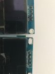
Just a note that may save some time and frustration.
I have been using an SSD1306 OLED Display for a while now and have no problems.
I recently had to order a few more and have found that the Ground and VCC pins on all of the new ones are reversed when compared to the original batch.

This is frustrating when you have already got a fabricated, tested and working PCB for your project.

Regards
Neil23804
 
Last edited:

AllyCat

Senior Member
Hi,

Yes, I noted that in post #25 of a thread a few weeks ago. In my case it appeared that the 32 x 128 (0.91") and 64 x 128 (0.96") were pinned differently and I assumed that might be a design difference. But now it just looks like "pot luck".

Normally, one would allocate "signals" next to an earth pin, but I2C is an "idle high" system (pull-up resistors) so there would be some justification in putting the (Data/Clock) signals next to Vdd. Of course when connecting I2C signals via twisted pairs, the recommendation is to make SDA and SCL each "share" with one of the supply rails (to reduce crosstalk between clock and data). But that implies yet another configuration (e.g. Supply and Ground at opposite ends of the header) which the nice little "RTC for Pi" module uses.

Looking further, I see that my "Weatherduino" project boards have GND and SDA at opposite ends of the headers, but the BMP/E 280 temperature/humidity breakouts, for example, have Vdd at the end. Another useful reference is that all the serial EEPROMs appear to have Vdd and SDA at opposite ends of their 4 pins (per side) package (and the intervening Write Protect is active Low), but then the PICaxe 08M2 has SDA and Ground at opposite ends.

So it looks as if there is no "standard", which confirms the decision I made for my little boards in the above post/thread, to provide for a row of "unscrambling" links in a convenient location. ;)

Cheers, Alan.
 

hippy

Ex-Staff (retired)
So it looks as if there is no "standard"
That is likely correct. The "SSD1306" is the controller chip but anyone making a board with an SSD1306 and OLED fitted is free to choose how they'll route the tracking and the connector pin order.

It would be nice if everyone copied everyone else so there was a de facto standard. That often happens but not always. Even with HD44780 LCD's it's not as standard as it could be. The pin order may sometimes be reversed with back light connections at either end.
 
Top