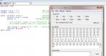
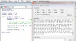
I tried to read range using srf05 in debug mode...but it always show the same range
why is it like this..i am not using sig mode..
Code:
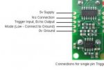
symbol trig = C.1 			; Define pin for Trigger & Echo (All M2, X2 parts)
symbol range = w1 			; 16 bit word variable for range

main:	pulsout trig,2 			; produce 20uS trigger pulse (must be minimum of 10uS)
	pulsin trig,1,range 		; measures the range in 10uS steps
	pause 20			; recharge period after ranging completes

	; now convert range to cm (divide by 5.8) or inches (divide by 14.8)
	; as picaxe cannot use 5.8, multiply by 10 then divide by 58 instead

	let range = range * 10 / 58	; multiply by 10 then divide by 58
	debug range			; display range via debug comm
goto main