SRF005 Ultrasonic Rangefinder
- Thread starter MurrayJ
- Start date

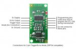
Heres the photo I am following, but to get it to work, I have to hook up the echo output to an input pin and the trigger Input pin to an output to get it to work.
Attachments
-
 25.1 KB Views: 37
hippy
Ex-Staff (retired)
It's a terminology issue more than anything, the descriptions are from the module's perspective; "Echo Output" is an output from the module so goes to a PICAXE input, "Trigger Input" is an input to the module so comes from a PICAXE output.
On the PICAXE side it would be sensible to label the two connections as "Echo Input" and "Trigger Output", then it becomes clear that an output from one is an input to the other.
On the PICAXE side it would be sensible to label the two connections as "Echo Input" and "Trigger Output", then it becomes clear that an output from one is an input to the other.
BeanieBots
Moderator
That's absolutely correct.Heres the photo I am following, but to get it to work, I have to hook up the echo output to an input pin and the trigger Input pin to an output to get it to work.
Consider it from the perspective of when you have the module in your hand.
"ECHO OUTPUT" is the OUTPUT from the module. Hence you connect it to the PICAXE INPUT. It describes the function of the pin on the device. It is NOT an instruction of where to connect it.
This is a standard way of labelling any equipment. Have a look at the back of your telly. Most (if not all) of the sockets will be labelled something like "Video In" or "Audio In". You connect them to the "Video/Audio" OUT on your video recorder.
The label refers to the device on which it is written.