I'm using a SMD 08M for a project and I"m a little short on IO. Not enough to use a bigger chip or an expander, but I'd like to do the following on 08M:
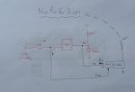
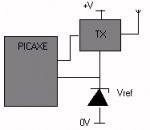
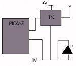
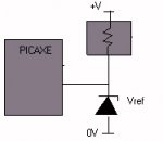
For pin3, which is either an ADC, IN, or OUTPUT - when I switch it to be an output, it powers the 5V pin of a 433 TX module. When I change it back to an INPUT, I want to read an ADC value from a 2.5V ref diode.
The two mini-circuits would of course be both wired up permanently. The picaxe code would only engage 1 at any given time, actually like a switch. My thoughts are around whether problems will occur.
For example - when the pin is an output, 5V will exit the pin and encounter 2 branches. The first goes to power the TX module. That's fine. The other branch will hit the anode of the reference diode, which will be sitting at 2.5V courtesy of a resistor attached to 5V. The resistor will be around 33K, as the ref diode only needs a fraction of a mA. Will problems occur with the 5V from the picaxe encountering the 2.5V from the reference diode? Will it stress the diode?
A similar situation will occur with another of the 08M's IO pins. Output - sending data to the TX module. On the input, reading the voltage from the 3.7V battery, again through a fairly substantial resistor. I'd expect the picaxe ADC should be comfortable with 0.5mA to make a reading, so assuming the voltage is around 3.7V, a 6K8 resistor or similar should be ok. In theory I could take the reading direct from the battery, but if this idea is going to work, a resistor in there would limit data signals getting pumped hard into to the 3.7V terminal .
It's late, so I'm a bit hazy at the moment. Any thoughts / suggestions / warnings before I blow up my little SMD 08M, much appreciated.
cheers all
")