Solar Mike
New Member
I am setting up an irrigation control system for a large commercial garden, initially there will be 10 or so solenoid valve controlled water lines that run sprinklers etc.
Most commercial controllers use AC systems with 22vac control signals activating solenoids; as our site is totally off grid and yet to get its big bank of batteries and inverter, I have decided to run all the external electronics from a 12V gel battery or similar, charged by a 100W PV panel.
Various types of 12vdc solenoids are available, we have decided to use the pulse latching type, these screw into the valve body and have 2 wires for activation. To open a water valve the solenoid is sent a 12vdc 150mS pulse, to later close the valve, another pulse of opposite polarity is sent; between pulses no power is consumed.
Initially I will be using small 12V rail mounted timers, one per solenoid, they typically have a small LCD screen and allow setting up to 15 or so time open periods per day, dead simple to setup; they have a single low current change over contact relay output.
Currently in NZ there are no off the shelf control systems that can pulse these solenoids, seems very strange as the solenoids are readily available, but nothing to control them. So I require a polarity reversing pulse driver that can scan the timer relay contact and turn on/off as required, this kind if control can be done with a DPDT relay and a pulse circuit or ditch the relay and use an "H-Bridge" arrangement to switch over the pulse polarity.
Two circuits have been designed and built/tested; one using a small pcb 8A DPDT relay and a 12 CD4093 schmitt trigger Nand gates to create the various time delay logic; the other using a Picaxe 08M2. I designed the Picaxe version first, then did the other; built them both to see what version was the easiest to make - remember I need 10 initially . The Picaxe version is by far the quickest to assemble, now that the software is working.
This thread will focus on the 08M2 version as it may interest some members here. Schematic below: Looks better when you click on it.
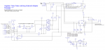
The 08M2 uses an opto isolated interface to the timer switch contacts or the output of a 22vac signal controller, the control lines can be 50M long, so I don't want that lot connecting direct to the cpu pins. The PAA140 is an isolated dual opti-mos switch, I seem to have a bin of them, so need using up, its input signals are ORed out as either could be used. Picaxe has some simple logic to read C.3 input signal, blink some LEDs and control the solenoid driver IC. DRV8871 has a lot inside it and can generate true H-Bridge output up to 45V and 3.6 amps. DRV8871 Spec The solenoids draw approx 2 amps @12v and can work between 9-24V. A 4700uf cap supplies the pulse current, thus the 12V battery power wires running to all pulse circuits can be quite thin; each pulse pcb is mounted close to its solenoid inside a water tight box with a clear lid, standby current is only a few mA.
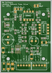
Everything fits on a double sided PCB 64 x 45mm, all components on the top.
Attached is the code as currently working, I haven't tested operation from a 22vac control signal yet, need to locate a transformer with correct voltage and plug onto a variac.
Cheers
Mike
Most commercial controllers use AC systems with 22vac control signals activating solenoids; as our site is totally off grid and yet to get its big bank of batteries and inverter, I have decided to run all the external electronics from a 12V gel battery or similar, charged by a 100W PV panel.
Various types of 12vdc solenoids are available, we have decided to use the pulse latching type, these screw into the valve body and have 2 wires for activation. To open a water valve the solenoid is sent a 12vdc 150mS pulse, to later close the valve, another pulse of opposite polarity is sent; between pulses no power is consumed.
Initially I will be using small 12V rail mounted timers, one per solenoid, they typically have a small LCD screen and allow setting up to 15 or so time open periods per day, dead simple to setup; they have a single low current change over contact relay output.
Currently in NZ there are no off the shelf control systems that can pulse these solenoids, seems very strange as the solenoids are readily available, but nothing to control them. So I require a polarity reversing pulse driver that can scan the timer relay contact and turn on/off as required, this kind if control can be done with a DPDT relay and a pulse circuit or ditch the relay and use an "H-Bridge" arrangement to switch over the pulse polarity.
Two circuits have been designed and built/tested; one using a small pcb 8A DPDT relay and a 12 CD4093 schmitt trigger Nand gates to create the various time delay logic; the other using a Picaxe 08M2. I designed the Picaxe version first, then did the other; built them both to see what version was the easiest to make - remember I need 10 initially . The Picaxe version is by far the quickest to assemble, now that the software is working.
This thread will focus on the 08M2 version as it may interest some members here. Schematic below: Looks better when you click on it.
The 08M2 uses an opto isolated interface to the timer switch contacts or the output of a 22vac signal controller, the control lines can be 50M long, so I don't want that lot connecting direct to the cpu pins. The PAA140 is an isolated dual opti-mos switch, I seem to have a bin of them, so need using up, its input signals are ORed out as either could be used. Picaxe has some simple logic to read C.3 input signal, blink some LEDs and control the solenoid driver IC. DRV8871 has a lot inside it and can generate true H-Bridge output up to 45V and 3.6 amps. DRV8871 Spec The solenoids draw approx 2 amps @12v and can work between 9-24V. A 4700uf cap supplies the pulse current, thus the 12V battery power wires running to all pulse circuits can be quite thin; each pulse pcb is mounted close to its solenoid inside a water tight box with a clear lid, standby current is only a few mA.
Everything fits on a double sided PCB 64 x 45mm, all components on the top.
Attached is the code as currently working, I haven't tested operation from a 22vac control signal yet, need to locate a transformer with correct voltage and plug onto a variac.
Cheers
Mike
Attachments
-
2.6 KB Views: 3