Solar charging 3 x AA NiMh

PaulRB

Senior Member
All, I want to use a small (80mm x 80mm) polycrystalline (judging by the dark brown colour) solar panel from my "box of bits" to trickle-charge 3 x AA NiMh cells.

The solar panel outputs up to just over 6V, open-circuit, when placed close up to a bright desk lamp.

Can I just wire the panel directly to the cells (via an IN1004 diode to prevent discharge overnight) ?

Or would this small panel be capable of over-charging and damaging the cells?

Thanks,

Paul
 

BeanieBots

Moderator
Can I just wire the panel directly to the cells (via an IN1004 diode to prevent discharge overnight) ?
Probably. It depends on the capacity of your AA cells.
As long as the panel current is less than one tenth of the capacity of your cells then there will be no problem.
 

PaulRB

Senior Member
Thanks beaniebots. Lets suppose the cells are 800mAhr to on the safe side, although they could be 2000mAhr.

What conditions should I measure the panel current under? Should I just connect a resistor to the panel outputs and measure the voltage drop? What value resistor?
 

John West

Senior Member
Under full sunlight, connect the panel to the current measuring inputs on a multimeter. Have the meter set on the highest range, then back it down until you're getting an accurate measurement of current flow. That will be your best-case current capability of the solar panel.

Be sure to take the reading with the panel facing full on toward the sun. Angled readings will be lower.
 

AllyCat

Senior Member
Hi,

Yes, the "short circuit" current is probably the best to measure. The current (for a fixed level of illumination) should be reasonably constant until the output gets up towards the open circuit voltage. But you may have to wait a few months for a "full" level of sunlight. ;)

polycrystalline (judging by the dark brown colour) solar panel
If it's a fairly even colour on (under) glass then it's probably amorphous silicon, which is only about 5% efficient. Polycrystalline usually have more obvious "panels" wired together and have nearer 10% efficiency.

Your panel is about 1/200 square metre, so at typically 800 W/m2 peak sunlight will receive about 4 watts. Thus perhaps a maximum of 400mW or 100mA output in bright sunlight. The only AA NiMh cells as low as 800mA that I've seen (recently) were in a Pound store! Most are now 2,000 - 3,000 mAhrs.

Cheers, Alan.
 

PaulRB

Senior Member
Thanks John. Substituting the desk lamp for the sun (I live in Yorkshire, so full sunlight can cause mass panic among the locals) I get a whopping 6.5mA. Lets be generous to the panel and assume real sunlight could double that, so 13mA.

Beaniebots, you were saying I should compare that with the capacity of the cells. That doesn't quite make sense to me, as one is a current and the other is a charge, but assuming we can trust it as a rule of thumb, it sounds like I don't need to worry about damaging the cells by overcharging!

Thanks all.
 

DamonHD

Senior Member
Hi

1) Sunlight could easily be orders of magnitude higher than internal lighting: our eyes respond logarithmically to cope.

2) Brown colour cells implies amorphous not any sort of crystalline.

Rgds

Damon
 

PaulRB

Senior Member
Cheers Alan. The panel came from one of those cheap LED garden shed lights. The LED unit also still works, but the circuit board seems to have gone home, because even with freshly charged batteries it would not come on. I dismantled it and threw the board away, but tested and kept the LED unit and solar panel. The original kit also had a remote control, which also failed. An 08m2 circuit will shortly replace it and the light will come on automatically at dusk for a timed period.

There, you see, not all my ideas are beyond my abilities!
 

AllyCat

Senior Member
Hi Paul,

Traditionally, a "ten hour rate" (i.e. charging at a current of 10% of the Ahr rating) has been considered "safe" for most battery technologies (at least to the entent that the cells shouldn't leak or explode). Normally, allowing for cell inefficiency, one would then terminate (or drop to trickle-) charging after about 14 hours, but it wasn't essential. However, excessive overcharging certainly won't do the cells any good, and I believe it's recommended that NiMHs should not be overcharged at a current above about C/20.

But a far more important way to be "kind" to the cells is not to excessively discharge them, so the real advantage of a PICaxe could be to terminate discharging at (say) 1.2 volts per cell (using calibadc10). I've been considering a similar (but more sophisticated) application and one way to "manage" multiple cells (if the PICaxe has two spare A/D input pins) is to put a resistor (perhaps 5 - 10 ohms) between the cells. The pins can then measure the current flow (voltage across the resistor) in both directions so could integrate (sum) the charge and discharge currents continuously, to ensure that the cells are neither excessivley over- or under- charged.

Cheers, Alan.
 

manuka

Senior Member
Perhaps post that PV wafer for an outing down under if you want trials under decent sunshine! I've just been testing some 20W types here in my NZ backyard,& (thanks to our scintillating summer) became almost sunstroked.
 

boriz

Senior Member
You can improve efficiency by eliminating the diode. The Picaxe can turn the charge on or off according to conditions.

EG: Picaxe measures photo-voltage [vP] and battery voltage [vB]

If vB < Bmax AND vP > vB THEN switch the charging current on.

If vB > Bmax OR vP < vB THEN switch charging off.

Also...

If vB < Bmin THEN disconnect load.

Where Bmax is the highest voltage that your pack can be charged to without damage, and Bmin is the lowest voltage your pack can be discharged to without damage.

Raising Bmin a little and dropping Bmax a little will improve the long term reliability at the cost of reduced capacity. This can easily be compensated for by using a larger capacity pack.

Also...

In sunny Yorkshire, you will probably never get the max rated output from your panel. Voltage or current. And likely much of the time your pack will receive very little charge. I recommend you use a larger panel with a larger voltage and current. EG: A 9v 40ma panel might only produce 4v 5ma on a cloudy day, still just enough for some charge. But the 6v panel would be useless. I'm generalizing of course, but you get the idea.
 

boriz

Senior Member
The Picaxe 'watchdog' can run at very low currents. Insignificant with WRT an 800mAH pack. So itself never needs to be turned off. And if you do use a diode, use a schottky type. It will drop only about a third of a silicon type.
 

boriz

Senior Member
It's no coincidence that I chose the 9v 40mA example. I have on the back-burner a similar project. It's a simple burglar deterrent 'fake' alarm box.

The nice professional looking alarm box will be fixed on the outside wall of my house, visible from the street. On the top surface of the box will be the 9v 40mA panel, and inside is a 3-cell cordless phone battery pack something like this, a Picaxe and a super-bright red LED.

The LED flashes at night with a low duty. Maybe 20mS on, 2000mS off. The Picaxe manages the charging and decides when it's nighttime based upon the panel voltage.

Completely wireless, automatic and maintenance free. Should work continuously for many years.
 

srnet

Senior Member
Traditionally, a "ten hour rate" (i.e. charging at a current of 10% of the Ahr rating) has been considered "safe" for most battery technologies (at least to the entent that the cells shouldn't leak or explode). Normally, allowing for cell inefficiency, one would then terminate (or drop to trickle-) charging after about 14 hours, but it wasn't essential. However, excessive overcharging certainly won't do the cells any good, and I believe it's recommended that NiMHs should not be overcharged at a current above about C/20
This is true, and the c/10 rule does apply to NiCd cells.

C\10 does in general apply to NiMh, but not for long periods. Recommendations vary between manufacturers see;

http://en.wikipedia.org/wiki/Nickel–metal_hydride_battery

So if a continuous rate of C\40 is to be used, the problem is that the charge time from flat may be excessively long even on sunny days.
 

BeanieBots

Moderator
Don't forget that the battery will also require some charge and the daylight is not 24hr so you probably get away with C/5 on very bright sunny days for the few hours it happens in the UK.
Of more concern is the battery life.
Anyone who has had solar garden lights will know that last about two years, three if you're lucky and then need new batteries.
No real surprise there. Garden lights typically discharge completely before morning and then only get partially charged.
This is not good for them. A typical life like that will be about 500 cycles.
Better to oversize the battery to avoid excessive discharge (don't forget a string of dull days) and charge at a rate that will give just a bit more than the required run time but is still below C/10 for those days when full charge is acheived.
 

boriz

Senior Member
Hey BB. I thought I'd said that already. Perhaps I wasn't clear.

Raising Bmin a little and dropping Bmax a little will improve the long term reliability at the cost of reduced capacity. This can easily be compensated for by using a larger capacity pack.
Max recharge cycles are sometimes quoted, but it's always a wild estimate. And it refers to complete charge-discharge cycles. It depends on the load and the panel of course, but an app like this is unlikely to go through complete cycles, further complicating matters.

With a larger-than-necessary capacity and a reduced charge 'span' (indicated above), you will get much more than the quoted number of cycles.

P.S.

A Picaxe controlled system as I suggested above also has the advantage of using all the available power from the panel. None is wasted in current limiting.
 
Last edited:

Haku

Senior Member
I reckon you can accomplish this for just over 2 quid.

Buy 2x solar garden lights from a pound store, wire the 2 panels in parallel to one circuitboard, also wire the batteries in parallel to the circuitboard and replace the LED with an automatic flashing one.

An upgrade would be using some 2000+ mah low self discharge NIMH's, they can hold their charge for weeks.
 

erco

Senior Member
You can improve efficiency by eliminating the diode. The Picaxe can turn the charge on or off according to conditions.
+1. Further improve efficiency by using a latching relay. Zero voltage drop between the solar panel and batteries, and the PicAxe just sends a brief blip to latch the relay on or off.
 

Jeremy Harris

Senior Member
This is true, and the c/10 rule does apply to NiCd cells.

C\10 does in general apply to NiMh, but not for long periods. Recommendations vary between manufacturers see;

http://en.wikipedia.org/wiki/Nickel–metal_hydride_battery

So if a continuous rate of C\40 is to be used, the problem is that the charge time from flat may be excessively long even on sunny days.
Very true, and well worth noting.

I made a serious error a few years ago by assuming that NiMH cells were like NiCd cells and would happily accept less than C1/10 for a fair period of time. I was very, very wrong, and nearly burned my house down. I was charging a pack made from 3.7Ah NiMH cells and turned the charge current down to about 200mA as a precaution for the remainder of an overnight charge (so about C1/18). I was woken at about 04.00 by a dull bang, followed by another a few seconds later. I went into my study to find the pack smoking, with two exploded cells. Luckily I was able to drag them outside by the charging leads, whereupon the pack caught fire in a series of violent explosions. Since then I have been extremely wary of overcharging NiMH cells. The photo below is of the pack after the fire.
 

Attachments

AllyCat

Senior Member
Buy 2x solar garden lights from a pound store, wire the 2 panels in parallel to one circuitboard, also wire the batteries in parallel to the circuitboard and replace the LED with an automatic flashing one.
Hi,

Probably better to wire the panels and batteries in series. These cheap garden lights actually use a voltage up-converter (the thing that looks like a resistor is actually an inductor) and the white LED (which drops/requires about 3 volts) is the "catching" diode. The more recent "colour changing" versions use/need an additional diode, with presumably there being sufficient supply rail capacitance within the colour-changing LED package itself.
____

I wonder how much of the "danger" of the more modern cell technologies is simply their higher energy densities. Once fully charged the energy has to go somewhere! 80mA into a typical 800mAhr AA NiCd would be about 100mW which can probably be easily dissipated from the can (at least in free air). But how many watts were continuously going into Jeremy's sealed battery pack?

Cheers, Alan.
 

Jeremy Harris

Senior Member
I wonder how much of the "danger" of the more modern cell technologies is simply their higher energy densities. Once fully charged the energy has to go somewhere! 80mA into a typical 800mAhr AA NiCd would be about 100mW which can probably be easily dissipated from the can (at least in free air). But how many watts were continuously going into Jeremy's sealed battery pack?

Cheers, Alan.
I pretty much determined the cause of the failure in that (pretty high power) pack. What happened was that one cell overheated due to being overcharged, which then melted the thin heatshrink sleeving around the cell case for that cell and an adjacent one (which would also have been quite hot). This allowed it to short out to it's neighbour (they were series connected), releasing a great deal of energy (these cells are capable of discharging at a few tens of amps quite easily). The result was a chain reaction, where more cells overheated and then shorted out, causing the rather spectacular fire.

I have a couple of solar powered sensors running in the garden, using 80 x 100mm "6V" panels charging a single 1600mAh NiMh cell, via a diode and a low value resistor. This system runs an 08M2 plus a CMOS 555 and 433MHz transmitter, via a step up converter/regulator to give 5V. The maximum charge current I can get is around 50mA on a very bright day, with a much lower average of around 20mA. The NiMH cell seems to tolerate being charged for long periods at C1/32 OK, I've found, as it's been working reliably for over a year now. I did find that I had to increase the battery capacity to cope with prolonged dull weather. When I first put these together I used 450mAh NiMH cells charging at about 30mA max and they wouldn't hold up after a few dull days (the average current drawn is around 4mA), but since switching to the 1600mA cells and the slightly higher charge current I've had no problems, even when it's very cold and dull for a few days.
 

BeanieBots

Moderator
Cells can sometimes develop an internal short which gives rise to a similar result. (even just sat on a desk!)
When cells are over charged it's not just the I*V dissipation that is of concern.
One of the electrodes is designed slightly larger than is required as a sacrifice which produces hydrogen at the other electrode.
Extra chemicals then recombine this back but there is a limit to the rate this can happen before the hydrogen is no longer re-absorbed and needs to vent as gas. This limit gets less with older/abused cells which is why there is often signs of venting on old cells even when they have been well treated.
 

PaulRB

Senior Member
You can improve efficiency by eliminating the diode. The Picaxe can turn the charge on or off according to conditions.

EG: Picaxe measures photo-voltage [vP] and battery voltage [vB]

If vB < Bmax AND vP > vB THEN switch the charging current on.

If vB > Bmax OR vP < vB THEN switch charging off.

Also...

If vB < Bmin THEN disconnect load.

Where Bmax is the highest voltage that your pack can be charged to without damage, and Bmin is the lowest voltage your pack can be discharged to without damage.
Thanks for that idea boriz. How would I do the switching? Bipolar or fet? Wouldn't the transistor drop as much voltage as a diode? Also, once the charging was switched on, won't vP and vB then match? Do I need to switch charging off regularly for a moment to re-test the voltages?

Thanks,

Paul
 

AllyCat

Senior Member
Hi Paul,

At lower voltages the solar cell basically delivers "constant current", so there should be no need to disconnect the cell before measuring the battery voltage. For the "6 volts" in your original post the choice of diode/bipolar/FET is probably not of much concern. Simplest (if available) is to use a Schottky diode which should drop about 300mV compared with 650mV of a typical diode. A saturated bipolar or a FET might drop only 100mV, but of course the bipolar needs some base current (chosen for the highest potential charging current).

However, the compromises become much more significant if recycling (or cannibalising) cheap Garden Solar lights. There, the PV panel is only about "2 volts" and the single 1.2 volt NiMH cell may require 1.5 volts when charging. In some tests, I found that putting a normal diode in series with the panel halved the charging current. But some of the cells did have a significant reverse leakage (in the dark), so it was debatable whether it would be better to tolerate, say, 500uA leakage over night than to halve the charging current during the day (hence the Schottky may be the best compromise).

My own planned application involves a voltage up-converter (running directly from the PV cell) but I'm still trying to decide whether it's worthwhile (or possible) for the PICaxe to control the mark-space ratio to optimise the input V and I for maximum power. I believe this can be worthwhile for crystalline panels, but it's more doubtful with the less well-defined "I/V knee" and low powers from an amorphous cell.

Cheers, Alan.
 

BeanieBots

Moderator
My own planned application involves a voltage up-converter (running directly from the PV cell) but I'm still trying to decide whether it's worthwhile (or possible) for the PICaxe to control the mark-space ratio to optimise the input V and I for maximum power.
At such low power levels the power needed to do the conversion is greater than the power gained from increased efficiency. I've tried it with both bipolar and FET. Simply not worth the effort.
The most efficient converter (for low power) is the simple buck converter. Even then, you need something like a 6v PV into a 1.2v (or possibly 2.4v) cell.
For an up converter the duty cycle is critical and the 10-bit PWM is not really up to the task. For a down converter the relationship is pretty much linear and much easy to control while trying to find the maximum power point.
Have a go anyway, It's a great learning curve and will teach you a lot about power conversion.
By far the best is (as has already been mentioned) to match the panel to the battery pack and switch it in/out with a latching relay but attempting to control the power conversion is far more fun!
 

PaulRB

Senior Member
Thanks Allan.

Done some testing this morning, the sun is indeed shining in Yorkshire!

Using an IN1004 diode, compared to wiring the pannel direct to the cells, only seems to loose about 0.1 ~ 0.2V, I expected more like 0.7V.

Sunshine does indeed give very different results to a desk lamp. In full sun the panel still only measures around 6.5V open circuit but around 75mA max current, so 10 times that for the desk lamp.

Charging the cells, I'm getting around 60mA at about 4V. The diode does not seem to make much difference in this situation. Covering the panel completely gives a reverse leakage current of around 30uA without the diode.

So should I bother with the diode or not?

I opened the panel's case but could not find a diode in there.

I would like to get the pixaxe to measure the light level by measuring the voltage from the panel. I could us an ldr for this but would then have to site the ldr on a length of wire, because the circuit will be inside. So using the panel to measure light level would be more convenient, and something slightly different to try.
 
Last edited:

inglewoodpete

Senior Member
I would like to get the pixaxe to measure the light level by measuring the voltage from the panel. I could us an ldr for this but would then have to site the ldr on a length of wire, because the circuit will be inside. So using the panel to measure light level would be more convenient, and something slightly different to try.
I have reservations about measuring the light level. It's more about maximising the charge current and minimising the losses, especially when dull or at night. Then measure the charge I & V: that will indicate the usable energy level. You will find the cleanness of the cell/panel and the angle of the sun, rather than the brighness of the light, are more important.

Rather than investing so much research into getting the most of your small panel, why not get a bigger one and waste a bit of the captured energy if necessary? You will probably need all the panel area you can get in a Yorkshire winter.
 

AllyCat

Senior Member
Hi Paul,

Personally I would use a series diode (since it probably won't reduce the charging current much) even though PV panels are inherently "diodes". The problem with normal diode reverse leakage is that it doubles for each 7 - 10 degrees rise in temperature, so it can become catastrophic even if it's almost unmeasurable at room temperature. However, the high reverse leakage that I measured in a few (not all) Garden Lights did not (fortunately) appear to increase with temperature, so it's presumably due to another cause.

I would like to get the pixaxe to measure the light level by measuring the voltage from the panel.
IMHO that's a non-starter, but you might get an indication of the light level by measuring the current. It depends for what purpose you want to measure the "light level" but amorphous panels (are said to) have the poor characteristic that they lose a significant amount of sensitivity over their life. However, their spectral response is basically similar to "normal" light whilst crystalline silicon extends into the Infra Red (presumably one of the reasons for its higher efficiency in PV applications, since approximately 50% of solar energy is in the IR).

@BB: Thanks for your comments. Yes, I'm sure what you say is true if the PWM runs in a "square wave" mode. But for the low currents (and low speed of a PICaxe) I expect to use a "sawtooth" current mode where the current may well fall to zero for periods between each switching cycle. Thus, (I believe) the actual PWM duty cycle is much less significant, but this is very much a "micropower" application, so it's just a "fun" challenge to see if I can manage by cannibalising one Garden Light and not two!

Cheers, Alan.
 

PaulRB

Senior Member
Pete & Alan, thanks for the feedback. But I don't really understand your concerns. Perhaps I haven't said enough about the application. I want to switch on the led lights at dusk for an hour or so. I want to use the voltage from the panel to detect the arrival of dusk, long after there is sufficient light to charge the cells. I will "teach" the picaxe what light level constitutes dusk with a pushbutton which will cause the picaxe to read the voltage and store the figure in eeprom. So as the panel's performance degrades over the years, I will have to repeat this operation occasionally.

Now I've explained, does that allay your concerns?

I have been playing around with the panel this afternoon in the sunshine with my dmm and I am getting the impression this idea will work fine.

20130302_175939.jpg
 
Last edited:

Hemi345

Senior Member
It might be worth it to add a n-channel mosfet between the solar panel and the connection to your 10K resistor that could short the panel to ground. This is how I did it for my window blinds project that uses 4x AA NiMH and two Parallax 6V 160mA panels connected in parallel to keep them charged. I check the battery voltage and if 5.1V, turn the mosfet on which shorts the panels to ground. Then when voltage drops to around 4.6V, it turns off the mosfet to allow charging again.
 

AllyCat

Senior Member
Now I've explained, does that allay your concerns?
Hi Paul,

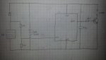
Yes the PICaxe and your circuit should work fine. Potentially far better than a typical "Solar Garden Light" because it can switch on at a (controllable) lower light level and can "manage" the battery better.

In my opinion most solar lights turn on at too high a light level (and thus run out of power too soon) but it obviously depends whether the light is intended only for "decorative" purposes or for a more practical reason. I'm sure that you (and most people) would say that your circuit is measuring the voltage produced by the solar panel. But I would argue that (once the light level is below the point where the diode is conducting*) it is actually measuring the current (through a 20 kohm resistance) produced by the panel. Since the PICaxe A/D converter voltage steps can be about 4mV (READADC10), you could resolve the PV current down to 0.2uA, which I guess it fairly dark!

But the main (potential) feature is not obvious from the circuit diagram, because the PICaxe (software) can monitor the battery voltage without using any external circuitry (using CALIBADC). In addition to switching off the load (which I assume is a LED + a series resitor) after a preset time, I would also terminate it if the supply voltage falls to less than (e.g.) 1.2 volts per cell. There is also the potential to dim the LED (PWM) if the PICaxe "knows" that the battery didn't get much charge during the day, or run brighter/longer if there's a risk that the battery will get over-charged.

* And when the diode IS conducting, the circuit is measuring the battery voltage (plus a diode forward drop).

Cheers, Alan.
 

PaulRB

Senior Member
But the main (potential) feature is not obvious from the circuit diagram, because the PICaxe (software) can monitor the battery voltage without using any external circuitry (using CALIBADC)
Ah! I was wondering if there was a way to do that...

The LED light unit has 10 white LEDs and what appear to be surface mount series resistors for each LED. The whole thing draws 250mA. I have the circuit working on breadboard as we speak. (can't construct it yet as have managed to run out of 8-pin sockets!). I used a BC635 to switch the light unit, with a 330R base-current limiting resistor, which seems to work fine, although a higher resistor would be better, maybe 1~2K. (Assuming gain of ~100 - I am learning slowly...)

I have also finally managed to find a use for a single 08M that has also been lurking in my box of bits. A tight squeeze to get the program in - only 14 byte variables and 256 bytes program space!
 

AllyCat

Senior Member
I have also finally managed to find a use for a single 08M that has also been lurking in my box of bits. A tight squeeze to get the program in - only 14 byte variables and 256 bytes program space!
Hi Paul,

... and no CALIBADC command in an 08M. :(

How long do you expect/hope that (~1 watt) LED unit will run each typical day from your 80mm square amorphous panel?

Cheers, Alan.
 

PaulRB

Senior Member
Well... I measured the pannel charging the cells at around 60mA in full sunshine. The lights use around 250mA and I probably will use 2000mAh cells. So if the cells are perfectly efficient, around 4 hours of full sun per day would run the lights for 1hr. If only 66% efficient, 6 hours full sun. Normal daylight may only give half the current of full sun (must measure this), so 12hrs needed. That's only available half the year. So its not looking great, have to see how things go. At least I will have put the components to work instead of sitting in a box.
 

Jeremy Harris

Senior Member
Remember that NiMH cells have a very strong depth of discharge to cycle life characteristic, one that is highly non-linear. If you regularly run them from, say, 100% state of charge to 10% state of charge then they will give a couple of hundred charge/discharge cycles at best, probably less. If you run them from 95% state of charge to 15% state of charge you might get a couple of thousand charge discharge cycles. If you do as they do in satellite battery packs, and run the cells over a state of charge/discharge range of less than 10% (typically they will only run between about 75% minimum and 80% maximum) then the cell life will be many tens of thousands of cycles. Hybrid cars are another example where they get fairly long cell cycle life by limiting the state of charge range between "fully" charged and "fully" discharged (the Prius, for example, can run its NiMH cells between about 20% minimum and 80% maximum, but in practice rarely lets the cells drop below about 50% charge in normal use).

If you over-size the battery pack, or incorporate an early switch off to stop it from discharging down to below about 30%, then the cells will last a great deal longer, even if you do still charge them to close to 100%. If you can limit charge so that you don't ever go above about 90% then life would also be improved a fair bit.
 

AllyCat

Senior Member
At least I will have put the components to work instead of sitting in a box.
Hi Paul,

Yes indeed, and maybe even produce some real facts (measurements) of the typical solar power available in the UK, which seems hard to find.

However, "theory" will probably give a good indication of the best that can be expected. Even with "clear skies", the "light level" in Winter is about half of that in Summer (due to passing through more atmosphere) and the useful day length about 4 - 5 hours against 12+ in Summer. So the energy available in Winter with clear skies would be only about 20% of that in Summer. Then, one of our Australian members was recently "surprised" that a dull day could reduce the power output by a factor of 10. So on a "bad" day (or might it be a week here in the UK?) in Winter you may get only perhaps 2% of the daily energy in Summer. So your original concern about overcharging the batteries of an "all-year" system may indeed be very relevant.

Even if you can't continuously monitor the input/output current (or energy), you might at least avoid discharging below 1.2 volts/cell (probably about 90% discharged). But this thread may need to get much longer, to decide how to do that with an 08M (not M2) and only a handful of bytes to spare. ;)

Cheers, Alan.
 

Jeremy Harris

Senior Member
Yes indeed, and maybe even produce some real facts (measurements) of the typical solar power available in the UK, which seems hard to find.
PVGIS is pretty accurate, certainly within a few percent of reality for much of the UK (and Europe). It isn't intended for small scale applications like this, but you can scale down the insolation data and still get a good prediction. See here: http://re.jrc.ec.europa.eu/pvgis/apps4/pvest.php
 

AllyCat

Senior Member
Hi Jeremy,

Thanks for that interesting link; I'll probably be forwarding it to a friend who's contemplating having PV panels installed, but I think bits like the following may give her a fit: :D

"The formula for estimating the relative efficiency used in Eq. 2 looks like this:
effrel(G',T'm)=1+k1ln(G')+k2ln(G')2 +k3T'm + k4T'mln(G') +k5T'mln(G')2 +k6T'm2 (5)
where G'=G/1000 and T'm=Tm-25."


Personally, I'll have a "play" with that calculator (also I'm writing a PICaxe program to calculate sunrise, sunset, solar elevation and expected clear-sky light levels in real-time) but it seems primarily concerned with maximising the power generation over a full year (and thus income from the FIT). It doesn't appear to help answer the question "How many consecutive days of rubbish light levels might occur, so that I can decide on the necessary capacity for my standby battery?" But that's probably an impossible question with so many variables concerning the battery and PV panel technologies, etc. and of course the British weather. ;)

Cheers, Alan.
 

Jeremy Harris

Senior Member
If you use the monthly or daily radiation predictions, together with the efficiency and orientation of your panel (14% is a pretty good average for ploy/monocrystalline true efficiency) then you can get a reasonably good estimate of output for any given period.
 

AllyCat

Senior Member
Hi,

Ah, I'd missed the "Stand Alone" tab. So I tried "plugging in" the figures that Paul has given earlier in the thread, using mA and mW instead of Watts and Amps. A nominal 300mW panel (75mA x 4v) and 1,000mWh load (1 hour at 250mA, 4v). That gave about 4 months when the battery was mainly "fully charged" and 4 months where it often became "discharged", with about the same amounts of energy being wasted (in Summer) and unavailable (in Winter).

But that didn't really indicate the time that the LEDs could run in winter, so I dropped the load to 500mWh and then 250mWh, the latter representing the LEDs running for 15 minutes a day. Then, there were just a few days in December and January when the battery became "discharged", but these days could just be accommodated by allowing the battery to fully discharge instead of stopping at the conservative (but recommended by several others above) of 40% charge remaining. However, even that 15 minutes is only possible because of the relatively large battery (2,000mAh) for a load of just 62mAh a day.

So now it's up to Paul to tell us if the predictions are correct. :) But it may take some time because it appears that the best months (for PV generation) are March - June. Clearer skies than in July and August, or a quirk of the computation?

Cheers, Alan.
 
Top