Smoothing Capacitor Value
- Thread starter lbenson
- Start date
westaust55
Moderator
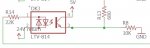
I believe that you may first need to consider the resistor on the 24 Vac side.
If sinusoidal, the peak voltage is around 35 Volts.
With a 22k resistor, the current when the waveform is at the peak will be around 1 mA -but only for a very short period.
The data sheet suggests to saturate the output transistor a If current through the LED input of 20 mA is required.
Typically, Going into saturation slows down the output transistor switching speed.
Then based on an rms voltage of 24 Vac and the 20 mA the resistor would be 24/0.02 = 1k2 Ohms.
As a broad brush idea, the pulses with then have a duty cycle of around 50% as opposed to say 1% when using a 22k Ohm resistor.
Once we know what you can/ must use for the input resistor and therefore the output transistor on duty cycle it is possible to consider the output side capacitor and resistor.
Hi,
It depends how quickly you want the logic input to respond to the on/off state. The optimum might be with about 10% ripple on the capacitor, which requires a Time Constant of about 80 ms (i.e.10 cycles of the 120 Hz). With a 10k shunt resistor that would need 8 uF, or say 10 uF for convenience.
For a PICaxe to read the filtered signal as a digital '1', the level needs to be more than about 2.0 volts, so assume it averages at least 2.2 volts, with 200 mV peak-peak ripple. Then the average drain current through 10k would be about 220 uA, but the minimum current transfer ratio of the optocoupler is only 20%, so you should assume an average diode current of at least 1.1 mA. 24 V rms is probably sufficiently greater than the photodiode forward drops that you should be able to calculate using the rms value, so the 22 k appears to be (just about) "good enough", at least with a current transfer ratio nearer to the nominal (100% ?).
The logic input signal may "dither" (000010101111) for a few cycles when the ac is first applied; you will need to handle that in the software, or apply a Schmitt Trigger (positive feedback) action. Note that the hysteresis of the PIC{axe} "ST" inputs is not as large as might be assumed from the data sheet and that mode would require a higher input voltage, maybe 4V, and a higher LED current.
Cheers, Alan.
Last edited:
lbenson
Senior Member
Thanks for the suggestions. I have just finished testing it and it works to my satisfaction with the resistors as shown with a 10uF smoothing capacitor.
I fed the output to pinC.3 on an 08M2, and ran a program which for 5 seconds at a time polled the input and counted transitions. I output with sertxd the final value of the pin and the number of transitions. Powering on the 08M2 with the 24VAC line conducting, I got a "1-1" followed by a string of "1-0"s, meaning pin high and no transitions. When I turned off the 24VAC, I got "1-52", "0-169", followed by a long string of "0-0", meaning no transitions from the OFF value. This was repeatable, so I appear to have a good sensor for transitions from OFF to ON and back over the course of 10 seconds, which is good enough for me (I will reduce the counting period for the real thing, but I didn't want to be overwhelmed with sertxd output).
I take the point about the higher duty cycle with lower-valued resistor on the 24VAC side, and will experiment with that when actually connected if the need arises.
Thanks again for the help.