Simple quick question

GeorgeSmith

New Member
Hello

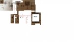
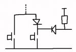
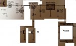
I am working on a circuit. Here is What I have so far - excuse all the white blocks on the image I deleted all the circuitry that was irrelevant to my question. S1 or S2 turn on the pixaxe. Basically I want to send a signal to the picaxe so it knows which switch was pressed. I was thinking of using a NPN transistor but I need some help.
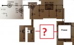
trans.jpg

Thanks in advance
 

Attachments

g6ejd

Senior Member
Well, there are a number of ways to do this, but because both switches are feeding the same point (an OR gate), you will need to connect your PICAXE to the switches themselves otherwsie you won't be able to detect which switch was activated. Assuming there is a voltage at the junction of the S1 and S2 and 1K R, then you could connect two R, one to each switch and then feed the junction of those to another R to form a potential divider to be read by the PICAXE on an ADC input, then varying the values of the two R would enable you to detect which switch, by the resultant voltage had been activiated and also determine if both had been activated. YOu may need tro add some series diodes with the two R to ensure there is no interaction between S1 and S2 when both are closed, although not essential. Conversely, use 2 PICAXE inputs with a pull up R on each (internal pull-ups) and connect the two switches to the inputs. Then detect which input is low when the S! or S2 is activated.
mods.jpg
 
Last edited:

GeorgeSmith

New Member
Thanks for the reply. I really appreciate. Is there anyway you could draw me a diagram. I am a bit confused!

Assuming there is a voltage at the junction of the S1 and S2 and 1K R, then you could connect two R, one to each switch and then feed the junction of those to another R to form a potential divider to be read by the PICAXE on an ADC input, then varying the values of the two R would enable you to detect which switch, by the resultant voltage had been activiated and also determine if both had been activated. YOu may need tro add some series diodes with the two R to ensure there is no interaction between S1 and S2 when both are closed, although not essential
 

GeorgeSmith

New Member
Sorry is your diagram for option 1 or option 2?

Option 1:
Assuming there is a voltage at the junction of the S1 and S2 and 1K R, then you could connect two R, one to each switch and then feed the junction of those to another R to form a potential divider to be read by the PICAXE on an ADC input, then varying the values of the two R would enable you to detect which switch, by the resultant voltage had been activiated and also determine if both had been activated. YOu may need tro add some series diodes with the two R to ensure there is no interaction between S1 and S2 when both are closed, although not essential
Option 2:

onversely, use 2 PICAXE inputs with a pull up R on each (internal pull-ups) and connect the two switches to the inputs. Then detect which input is low when the S! or S2 is activated.
Thanks
 

hippy

Technical Support
Staff member
You can possibly do it with a couple of diodes ...
How does this circuit work?
Basically the pull-up on the right holds the PICAXE input high, but when the right hand switch is pressed it pulls that input pretty close to 0V through the right hand diode, low enough that the PICAXE input reads low and can tell that switch was pushed. If it starts and the input isn't low then it must have been started by the other switch.

The diode above the right hand switch works in a similar way allowing that switch to bring the transistor base close to 0V - hopefully activating whatever the rest of the circuit does. It also prevents the left hand switch from pulling the PICAXE input low when it is pushed, but the left hand switch still pulls the transistor base to 0V.
 

Billo

Senior Member
A couple of questions.

1) Do you intend that the PICAXE based circuit will only be on while the PB is pushed?
2) How much current do expect the PICAXE based circuit to draw?
 

GeorgeSmith

New Member
1) Yeah. S1 is a push switch - have to hold it down to keep the picaxe on. S2 is flick switch - once it has been flicked the picaxe will remain on until it is flicked back.
2) I'm not too sure about the answer to that one.

I have two modes:

- 1. Picaxe on while S1 is held down. When S1 is held down the picaxe will control some outputs (ie turn on an LED for example). I don't want the picaxe to stay on for long and drain the battery. I might only hold S1 down for 2 seconds.
- 2. Picaxe on when S2 is flicked. I want the picaxe to stay on for long periods of time (I don't want to hold down S1 down for a long time). The picaxe will control other outputs.

If S2 is flicked would it matter is S1 is pushed assuming I used one of the circuits that was provided above? I want S2 to have preference over S1. So if S2 is flicked the picaxe will know that it is mode 2 and pushing S1 won't change it to mode 1.

The circuit that I attached is my whole circuit apart from 2 inputs and 1 output. They have no impact on the circuitry that I have given

Thanks
 
Last edited:

srnet

Senior Member
Between the point where the two switches are connected and the 1K resistor to the base of the transistor there is a junction shown , but whats connected has been removed from the circuit diagram.

What is connected there ?
 

GeorgeSmith

New Member
Nothing is connected there. I used an old image to make this. My circuit is what you see. All the bits removed aren't part of my circuit.

Thanks
 

fernando_g

Senior Member
1) I have two modes:

- 1. Picaxe on while S1 is held down. When S1 is held down the picaxe will control some outputs (ie turn on an LED for example). I don't want the picaxe to stay on for long and drain the battery. I might only hold S1 down for 2 seconds.
- 2. Picaxe on when S2 is flicked. I want the picaxe to stay on for long periods of time (I don't want to hold down S1 down for a long time). The picaxe will control other outputs.
Thanks
Hippy's circuit will then work exactly as you require. You only have to write code such that as the picaxe starts up, the very first thing it does is to test whether the port has a "0" or not. Branch to other code accordingly.
Simple as;

IF B.1= 0 then
goto myroutine_0
endif
goto myroutine_1
 
Top