simple power controller (08-m)

boelle

Member
for the past days i have struggled with a power controller, the functions are:

1. when pin 3 goes high it checks if its still high after 3 secs, if that is the case it activates relay 1 after another 5 secs and relay 2 after 5 more secs

2. when pin 3 goes low it shuld hold the relays for 20 secs.

there are also a rutine to check for battery voltage.

the setup is used to power up a car pc when acc lines goes high and to cut power 20 secs after acc line goes low.

the power up sequence is spot on as i want it, but power is cut as soon as acc goes low.

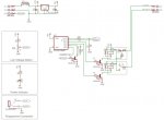
my schematic are below (disregard the programmng connector), the program in the picaxe:

Code:
boot:

Symbol Whole_2 = B11
Symbol Fract_2 = B12
Symbol C = B3 		      ;Var used to detect if the initial 3 sec acc line check has been done
Symbol T = B0		      ;Counter used in for next loop
C = 0					;Reset C
T = 0			            ;Reset T
Low 1	                        ;Turn off AMP
Low 2	                        ;Turn off PC
ReadADC 4 , B1		      ;Read the battery voltage and store it in B1

Whole_2 = B1 * 5 * 4 / 255        'Whole number
Fract_2 = B1 * 5 * 4 * 100 / 255 // 100       'Digits 
SerTxD ("Battery:  ",#Whole_2, ".", #Fract_2)


If B1 < 141 Then battlow	;Battery voltage is too low - Adjust value after < to fit your needs, if voltage is ok program will just continue on next line.                                Otherwise it will jump to battlow section
B2 = Pin3                     ;Store status of ACC Line in B2
If B2 = 1 Then boot	      ;Go to start of boot section
If B2 = 0 Then ignon	      ;Go to ignon section


main:

ReadADC 4, B1		      ;Read the battery voltage and store it in B1

Whole_2 = B1 * 5 * 4 / 255        'Whole number
Fract_2 = B1 * 5 * 4 * 100 / 255 // 100       'Digits
SerTxD ("Battery:  ",#Whole_2, ".", #Fract_2)

B2 = Pin3		            ;Store status of ACC Line in B2
If B1 < 141 Then battlow	;Battery voltage is too low - Adjust value after < to fit your needs
If B2 = 1 Then ignoff	      ;Go to IgnOff Section
If B2 = 0 Then ignon	      ;Go to IgnOn section

ignoff:
	
Pause 20000 	            ;Wait for 20 seconds
low 2	                        ;Turn off PC
low 1	                        ;Turn off AMP
	
Goto boot		            ;Got to the boot section

ignon:

If C > 0 Then main	      ;Jump to main section if the acc line has been on for at least 3 sec's without interrupt ie crank engine
For T = 0 to 3		      ;The next 3 lines put 3 sec wait in to the loop
Pause 1000
Next
B2 = Pin3		            ;Store status of ACC Line in B2
If B2 = 1 Then boot	      ;If Acc line is low then go to boot, this will reset C and we start over, otherwise the program will continue
C = C + 1		            ;Add 1 to C, once this is done it will skip the the ignon part because the first line will kick it back the main section
Pause 5000 	                  ;Wait for 5 seconds, adjust as needed
High 1		            ;Turn on PC
Pause 5000 	                  ;Wait for 5 seconds, adjust as needed
High 2		            ;Turn on AMP

Goto main

battlow:

Low 2			            ;Turn off PC
Low 1			            ;Turn off AMP
ReadADC 4, B1		      ;Read the battery voltage and store it in B1

Whole_2 = B1 * 5 * 4 / 255        'Whole number
Fract_2 = B1 * 5 * 4 * 100 / 255 // 100       'Digits
SerTxD ("Battery:  ",#Whole_2, ".", #Fract_2)

If B1 > 166 Then boot 	      ;Adjust value after > to fit your needs - Tells when its ok to return to normal, until the voltage goes over this value the program                            will stay here. Once voltage is ok it will start from the boot section


Goto battlow
Strange enough it works in simulator but not in real life...
 

Attachments

Last edited:

john2051

New Member
re:

Hi, I like the circuit diagram, it looks very professional. The only thing I can see may cause problems is the program socket wiring. I might be wrong, but i thought the tip was ground.

Which program are you using the draw the cct diagrams?

regards....John
 

techElder

Well-known member
Classic spaghetti code. Difficult to follow some of your reasoning.

Why do you check your voltage and branch so many different places?

A subroutine with the battery check and branch code would go a long way to troubleshooting your code.

It's difficult to even draw a flow chart from what you have posted. Have you done that?
 

boelle

Member
Hi, I like the circuit diagram, it looks very professional. The only thing I can see may cause problems is the program socket wiring. I might be wrong, but i thought the tip was ground.

Which program are you using the draw the cct diagrams?

regards....John
The programming socket is wrong, i discovered it to late, it was first when the pcb was pro made i figured it out, but a minijack extension cord was cut up to correct the mistake

I had a friend in the us do this one, he uses eagle to do both schematic and pcb
 

boelle

Member
Classic spaghetti code. Difficult to follow some of your reasoning.

Why do you check your voltage and branch so many different places?

A subroutine with the battery check and branch code would go a long way to troubleshooting your code.

It's difficult to even draw a flow chart from what you have posted. Have you done that?
it was the only way i could hammer up something quickly that i could understand just a bit, but i disccovered that there are a bug in my way of doing this

a little explaing of the code:

Boot section is where the program will start, it makes sure that both pc and amp's are off and then it waits for the pin 3, at the same time it checks if voltage is to low if that is the case it jumps to the batlow section where it will stay until volts are ok again

if pin3 goes high it jumps to the ignon section, here it will wait 3 secs and check if pin3 is still high, if that is the case it will add a value of 1 to C and then wait 5 secs and turn on pc, and after 5 more secs it turns on amps, after that it jumps to main section, here nothing will happen as long pin3 is high since C are now higher than 0.

so far that works, but the power down sequence does not work but it should be like this, in the main section it will now detect that pin3 is low and that should make it jump to the ignoff section, here it should wait for 20 sec before it turn of the relays and jump back to the boot section

instead it turn of the relays instantly, making me belive it jumps to boot section instead og ignoff, i just cant figure out why
 

boelle

Member
just playing arround with flowchart, how do i make the read voltage part? i can read the voltage, but cant figure how to do part that tells the code to jump... i have tried flowchart more than once before but always gave up on it
 

boelle

Member
i did another simulation.... it works in simulation but not when transfered to picaxe and tested in real situations
 

hippy

Ex-Staff (retired)
It is very hard to follow the code so it may be worthwhile rewriting it in a simpler fashion, simulating that then running on hardware to get the simpler program working then adding extra capabilities as you progress, designing, simulating testing on hardware.

Certain things such as ...

For T = 0 to 3
Pause 1000
Next

Would be better expressed as "PAUSE 4000", and -

B2 = Pin3 ;Store status of ACC Line in B2
If B2 = 1 Then boot

could be better expressed as -

If pin3 = 1 Then boot

and perhaps even better as -

If ACC_INPUT = IGNITION_ON Then boot

or similar, with ACC_INPUT and IGNITION_ON defined by SYMBOL statements.

I would suggest writing the code just to handle the power-up and power down sequence first, then add battery voltage checking when that's working. I'd also test with LED's+R rather than relays.
 

boelle

Member
my ONLY problem is the power down sequence, it does not wait the 20 secs but cut the power instant.... power up is ok

and i cant use LED's as i'm running in a done PCB
 

boelle

Member
btw... battery voltage checking are also working

ie if i just add power and let it do the powerup part and i turn my supply down it will at some point cut power like it should
 

Pauldesign

Senior Member
Did you first run your code in the simulator and see if it works as you wanted?

If not, i reckon you do so. You may add a break point just after the the subroutine where the program must wait for 20s. Optionally you may simulate your code manually.

Note; you may only program your PICAXE once you happy with the simulated result.

Syntax checker;Simulator and Program are in that order in PE for a reason, so please make use of it.

I prefer to use gosub instead of goto when calling a subroutine.

Alternatively you may use wait 20 instead of pause 20000

Just some tips though...;)
 

boelle

Member
tried to reverse all high and low commands.. ie low changed to high and high to low

so with the acc line low relays are on.... when acc goes high it takes some time before the relays are deactivated.... but as soon acc goes low the relays change.... should at least take 5 secs for them to change....
 

Pauldesign

Senior Member
Don't hang yourself but maybe the 08M PICAXE ;), is part of the learning experience; I had lots of such situations before.

Try a different 08M or other compatible PICAXE and see if it helps.
 

techElder

Well-known member
my ONLY problem is the power down sequence, it does not wait the 20 secs but cut the power instant.... power up is ok

and i cant use LED's as i'm running in a done PCB
Everything you are saying and doing in this thread points to the problem with not using structured code.

You can't separate functions and test them separately.

Get away from using GOTOs in your code and learn to use GOSUBs. Break your project down into separate functions. Create subroutines for the various functions. Then you can isolate problems to fix them.

Learn to use SYMBOLS to your advantage.

EVEN IF you have something that works now. In 6 months even you won't be able to tell what's going on in your program.
 

Pauldesign

Senior Member
Lessons #3, never buy 1 PICAXE or any electronic IC; at least 2. :)

Okay my Plan C, is to download a new simple code such toggle 0 and see if the 08M operation changes. If it does then, re-download your code and see if the code functionality changes as you wanted.

If it doesn't, try to practical test only the part of the code that work on the simulator and not on 08M and see if it works on its own in the 08M.

Then you may proceed to integrate other section of the code, test and see if they work, until you might find the dead code or what is causing the problem.
 

boelle

Member
trying to make a very simple on / off thing without timers

then adding timers

but sure the trash pin is ready... problem is that i'm shit at programming and i might come to where i just give up
 

Pauldesign

Senior Member
Well in Electronics we don't just give up if things doesn't work, you've to troubleshoot and if possible start from scratch.

Well, the choice is yours and please don't tell me your parent or somebody persuaded you to study electronics otherwise you're in the wrong field and if this forum can't help you, then you're not just serious and no other electronic related forum will help u. Things doesn't just work by chance, although sometimes they do:rolleyes: and maybe just once.

I guarantee you that the feeling you'll get if you fault find your code and get it to work as you wanted is like having that very first date and later on sealing the deal :D
 

boelle

Member
nah i picked the picaxe for this as it was the cheapest way to do what i want... i could go for a PSU with built in controller but they are way to expensive

on another note i did manage to make a simple loop that turns the relays on and off, that at least is working
 

hippy

Ex-Staff (retired)
but sure the trash pin is ready... problem is that i'm shit at programming and i might come to where i just give up
It's much like learning to swim. If you paddle around for a while, going further each time, you'll find it was easy. Dive in and be out of your depth and it can easily put you off for life.

This is why we are suggesting simplification, taking a step back and approaching it in a step-by-step manner. Writing a large or complicated program which works under simulation is much like writing a musical score or a recipe without trying that in practice as you go. The end results may be very disappointing when it should have worked.

One of the problems with the quantity and structure of your code is that it's not easy for anyone to tell why it may be failing. It may indeed be a simple problem but it's hard for others to determine.
 

boelle

Member
trying to make it more simple and test at each step, so far the code is:

Code:
boot:

Symbol C = B3 		      ;Var used to detect if the initial 3 sec acc line check has been done
C = 0					;Reset C
Low 1	                        ;Turn off AMP
Low 2	                        ;Turn off PC
B2 = Pin3                     ;Store status of ACC Line in B2
If B2 = 1 Then boot	      ;Go to start of boot section
If B2 = 0 Then ignon	      ;Go to ignon section


main:

B2 = Pin3		            ;Store status of ACC Line in B2
If B2 = 1 Then ignoff	      ;Go to IgnOff Section
If B2 = 0 Then ignon	      ;Go to IgnOn section

ignoff:
	
Wait 20      	            ;Wait for 20 seconds
low 2	                        ;Turn off PC
low 1	                        ;Turn off AMP
	
Goto boot		            ;Got to the boot section

ignon:

If C > 0 Then main	      ;Jump to main section if the acc line has been on for at least 3 sec's without interrupt ie crank engine
Wait 4
B2 = Pin3		            ;Store status of ACC Line in B2
If B2 = 1 Then boot	      ;If Acc line is low then go to boot, this will reset C and we start over, otherwise the program will continue
C = C + 1		            ;Add 1 to C, once this is done it will skip the the ignon part because the first line will kick it back the main section
Wait 5 	                  ;Wait for 5 seconds, adjust as needed
High 1		            ;Turn on PC
Wait 5 	                  ;Wait for 5 seconds, adjust as needed
High 2		            ;Turn on AMP

Goto main
Very simple but still no joy at the power down part
 

boelle

Member
dooh... found the error... it was the controller that was somehow wired wrong

i would call myself a twat but i dont think that covers it
:p
 

1968neil

Senior Member
try the following code,
After studying the code for a bit i see that when the battery volts go low the PC shuts off straight away....

If you use a second if - then ReadADC to tell it what to do if the battery is low, then goto Ign-Off it will shut down after the required 20 seconds ?

Hope i understand what you meant ?
Hope this helps.
Regards

Neil

Code:
boot:

Symbol Whole_2 = B11
Symbol Fract_2 = B12
Symbol C = B3 		      ;Var used to detect if the initial 3 sec acc line check has been done
Symbol T = B0		      ;Counter used in for next loop
C = 0					;Reset C
T = 0			            ;Reset T
Low 1	                        ;Turn off AMP
Low 2	                        ;Turn off PC
ReadADC 4 , B1		      ;Read the battery voltage and store it in B1

Whole_2 = B1 * 5 * 4 / 255        'Whole number
Fract_2 = B1 * 5 * 4 * 100 / 255 // 100       'Digits 
SerTxD ("Battery:  ",#Whole_2, ".", #Fract_2)


If B1 < 141 Then battlow	;Battery voltage is too low - Adjust value after < to fit your needs, if voltage is ok program will just continue on next line.                                Otherwise it will jump to battlow section
B2 = Pin3                     ;Store status of ACC Line in B2
If B2 = 1 Then boot	      ;Go to start of boot section
If B2 = 0 Then ignon	      ;Go to ignon section


main:

ReadADC 4, B1		      ;Read the battery voltage and store it in B1

Whole_2 = B1 * 5 * 4 / 255        'Whole number
Fract_2 = B1 * 5 * 4 * 100 / 255 // 100       'Digits
SerTxD ("Battery:  ",#Whole_2, ".", #Fract_2)

B2 = Pin3		            ;Store status of ACC Line in B2
If B1 < 141 Then battlow	;Battery voltage is too low - Adjust value after < to fit your needs
If B2 = 1 Then ignoff	      ;Go to IgnOff Section
If B2 = 0 Then ignon	      ;Go to IgnOn section

ignoff:
	
Pause 20000 	            ;Wait for 20 seconds
low 2	                        ;Turn off PC
low 1	                        ;Turn off AMP
	
Goto boot		            ;Got to the boot section

ignon:

If C > 0 Then main	      ;Jump to main section if the acc line has been on for at least 3 sec's without interrupt ie crank engine
For T = 0 to 3		      ;The next 3 lines put 3 sec wait in to the loop
Pause 1000
Next
B2 = Pin3		            ;Store status of ACC Line in B2
If B2 = 1 Then boot	      ;If Acc line is low then go to boot, this will reset C and we start over, otherwise the program will continue
C = C + 1		            ;Add 1 to C, once this is done it will skip the the ignon part because the first line will kick it back the main section
Pause 5000 	                  ;Wait for 5 seconds, adjust as needed
High 1		            ;Turn on PC
Pause 5000 	                  ;Wait for 5 seconds, adjust as needed
High 2		            ;Turn on AMP

Goto main

battlow:

ReadADC 4, B1		      ;Read the battery voltage and store it in B1

Whole_2 = B1 * 5 * 4 / 255        'Whole number
Fract_2 = B1 * 5 * 4 * 100 / 255 // 100       'Digits
SerTxD ("Battery:  ",#Whole_2, ".", #Fract_2)

If B1 > 166 Then boot 	      ;Adjust value after > to fit your needs - Tells when its ok to return to normal, until the voltage goes over this value the program                            will stay here. Once voltage is ok it will start from the boot section

If B1 < 141 Then ignoff  	;Battery voltage is too low
Goto battlow
 

boelle

Member
the idea is to kill the pc without notice if volts go low, its a kind of protection if something is draining the battery, if both the battery and generator are healthy this should never happen anyway. it happend to my old test battery it will to quickly go low, but adding a charger makes it work.
 

boelle

Member
the BIG fault was how i have wired in the controller to the ACC line, in my case i just needed to add a 1n4001 diode on the ACC line, then everything worked like i wanted, it was just not the first place I could imagine the the diode was needed
 
Top