Simple Picaxe LED driver.

Shafto

Senior Member
For running an LED off of a 3.7V nominal Li-Ion rechargeable battery (4.2V-2.7V) I have been using 0.12V drop 350mA Linear regulators in parallel combinations for differerent drive currents.

I had an idea though, now that I've learned how FETs actually work from the switch that I made, to build a PWM/Direct drive LED driver. The plan is to supply the picaxe with a constant 2.5V from the reference so it can accurately measure the voltage drop across the current sense resistor.


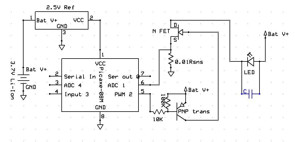
By measuring the voltage and determining the instantaneous current flowing, I want to use PWM to lower the average current to LED spec, and then have the duty cycle increase as battery voltage and current drop, to maintain average current, until battery voltage drops to LED voltage, the PWM duty cycle goes to 100%, and the LED is directly driven from the battery through the FET.

So for instance, if I'm using an LED with a voltage drop of ~3.6V@5A and the fresh battery voltage sags to 3.7V under a 5A load (typical) The LED will be seeing about 10A, so the Picaxe would run the FET at 50% duty cycle to start.

A capacitor on the output would lower the ripple current on the LED during the PWM phase, increasing it's efficiency, I'd have to find out what frequency I want to use to determine how big the capacitor should be and such, I didn't include it in the schematic.

So, does this sound feasible? I'm sure there would be trial and error programming and such, and quite a few questions from me along the way, but if I'm on to something that will actually work here and not just some useless hair-brain scheme then I'd like to give it a try, I think I'd learn quite a bit.
 
Last edited:

Dippy

Moderator
From what I can gather it seems you are trying to make a simple buck cc regulator.
Note: The image wasn't there when i started typing... now it has magically appeared.

If you are trying cycle-by-cycle ADC of fast PWM then good luck.
If you Fq is high and duty low your sampling would have to hellish fast.
You would need to synch the ADC start to PWM for true c-by-c and I don't think PICAXE is fast enough.

Your MOSFET drive is inadequate for efficient driving. You need a push-pull driver.
And I'm not sure if that PNP would switch off properly either with your dual-voltage arrangment.
Either a complimentary pair (well matched) or a pukka MOSFET driver.

I'm not sure how this output capacitor will help efficiency (Can't see it in schematic??) , but it would certainly assist your current sensing by smoothing things. And it could certainly reduce some noise. However, with the current you mention you may need something healthy.

May I suggest that you look at Nat Semi and Zetex (Diodes Inc.) LED controllers which do what you want to do . I realise you want to make your own but, at the very least, the Data Sheets will give you a head start in designing an efficient circuit AND give you some idea of component values.
Efficiency requires a bit more than stuffing in components that look right ;)

I really would recommend you look at switched-mode (inductorised) techniques - the designs are well established and developed.

What do you reckon BB?
 
Last edited:

Shafto

Senior Member
I suspected driving the FET might be a problem, as I've heard of "FET" drivers and such. I don't exactly understand why anything more complicated than +V for on and pulled down to GND for off is needed, but I'll look into it.

None of the ready made buck drivers I have seen work like this, they all use inductors/capacitors and have a voltage drop to the LED. The point of this one is that it can "buck" the current down, and then go into direct drive with no voltage drop (other than from resistance in the FET and the Rsns).

Capacitor isn't in schematic, and I didn't mean that it would effect the efficiency of the circuit, it would make the LED preform more efficiently, as it would lower the average current through the LED.

I'm not exactly sure what I'm trying yet. Cycle by Cycle may require too much computing, maybe something more crude if possible? precision control isn't necessary. Maybe take a sample every 10 or 100 cycles?

I have built some LED drivers from datasheets before, so I am somewhat familiar with them and the usual component values.
 
Last edited:

BeanieBots

Moderator
Not a hair-brain scheme at all. As Dippy points out, it's a very well established (well over 40 years) method of voltage conversion.
As suggested, look up "buck", "boost" and "flyback" converters. The 'normal' method is to use inductive methods to store/release the energy during the on/off times.

For some reason I cannot see the diagram.
 

Shafto

Senior Member
I think my photo host is acting up right now, I'm having problems too. Hopefully it'll work itself out soon.

Inductors and capacitors are large, and I don't really have the room. My main reason as I stated though, is to go with a driver that can go into direct drive when the battery voltage drops to the same as the LED voltage, and continue like that until the battery is dead.

If I was going to go with a switched mode inductor/capacitor setup I'd need to use a buck-boost driver to lower the voltage, and then boost it when battery voltage falls to LED voltage (and eventually bellow). This would give full regulation until the battery was dead, but for 5A of current it's far too expensive, large, and complex.

I think using a simple buck driver than drops the current through PWM until battery voltage is the same as LED voltage, and then current will just slowly drop on it's own as the battery depletes until dead. The LED won't be in full regulation the whole time, but that's an ok compromise, it's nice to know when lithium batteries are starting to get low anyway, by the light fading, as you shouldn't let them get too far depleted.


Now my programming skills are very basic, my plan is for projects like this to improve them!

I was thinking though, that a lookup table with current output corresponding to the appropriate duty cycle could be checked every 100 cycles or so. The battery voltage won't be erratic, and will fall at a predictable rate, so I don't think it'll be a problem. So the picaxe looks at the voltage drop on the resistor, calculates current, looks it up in the table, finds the duty cycle for that current, say 50%, runs at 50% for 100 (maybe more) cycles, and then checks the current again and possibly applies a higher duty cycle if current has dropped enough.

100 cycles might even be more than plenty, transients aren't going to be an issue here, so no fast response needed. Voltage will be falling anyway, so if the Picaxe is too slow to react to raise the duty cycle, all that will happen is current will slightly drop, no big deal.
 
Last edited:

BeanieBots

Moderator
Inductors don't need to be big.
With LEDs & battery power becoming more popular and the power requirements of mobile phones needing to have small solutions, there are now a whole host of ready made solutions available. By using switching speeds of several megahertz, the inductors can be very small and so can the caps.

You should be able to find something that suits your need almost ready made which you could drive with PWM to give variable brightness.

If you opt not to use any inductive methods then efficiency will be the same as any other linear method, so IMHO it would not be worth using any clever PWM technique over a simple low dropout regulator method.
 

Dippy

Moderator
The image has disappeared for me again (try tinypic.com or 'Manage Attachments' button below).

BEFORE you get to coding you have to sort out your circuit.
I really think your Task No.1 is to read up on MOSFET driving and MOSFET specification.
No point spending time coding if your circuit is dodgy.


Your drive ciruit (from memory) seems way out. EDIT: Oh, it's back again.
Your PNP drive (if memory serves me and if it works properly) can make the Gate go high, but how does it drive it down?
Gates have capacitance. If you want speed -which you do- you have to push-pull. Up/down and in/out fast and furious.
And instantaneous currents (remember 'charge'?) will be high.
So, you'll need to change your drive circuit.

Then look at your absolute voltage levels.
Compare them to the Vgs values in the Data Sheet of your favourite MOSFET.
Will the chosen MOSFET switch fully to a reasonably low Rds?
If not, then your current switching will be poor and inefficient = poor lighting and hot FET.

You may find a low gate voltage MOSFET kicking around somewhere. Be AWARE that low gate 'threshold' isn't the only parameter you should check. Look at the Characteristics graphs/tables to calculate the R at certain Gate voltages.

Actual driving (the principle and discussion) has been coverd in this Forum many, many times. Have a search.
 
Last edited:

Shafto

Senior Member
Linear regulators are actually very efficient for driving an LED from a single Li-Ion cell, especially with a higher load like 5A. The battery voltage drops to just over the LED voltage under the load, and barely any is burnt off. That slight bit of over-voltage though would cause a huge amount more current to flow in a 5A LED with a very large die surface area, so it needs to be controlled, and right now I'm wasting 0.12V to do it.

If I could use this PWM buck driver to control the current while the battery voltage is over the LED voltage, and then go direct drive, with no 0.12V overhead, my mission would be accomplished.

Having said all that though, I had figured that using PWM control would be more efficient than straight linear drive, as I would be using the extra voltage to drive more current into the LED at a lower duty cycle than 100% linear, therefore I would be using the extra voltage in the LED, not just burning it off. I could have it totally wrong though!


Edit #1. I forgot a pull up resistor for the PNP transistor that drives the FET. I'll have to look into FET drive and why this is inadequate. I was thinking ~50khz would be sufficient, but if it's easy to increase that to lower the capacitance that would be better. I changed the schematic, added the pull up resistor and the capacitor for the LED.

Edit #2. I was planning to use the same MOSFET I used in the switch I made: http://www.infineon.com/dgdl/BSC026N02KS+G+Rev1.05.pdf?folderId=db3a3043163797a6011637c252b10018&fileId=db3a3043163797a6011637c2a4280019

It behaves very well at low voltage.
 
Last edited:

Dippy

Moderator
Yes, the gate voltage o/p characteristics specs look good.

Have you seen the input capacitance?
Imagine the brief currents involved switching that charge on and off 50k times per second.
Your instantaneous currents will be high (albeit very brief).
A (possibly weedy) signal level transistor can't do that well.
And a simple pull-up resistor will only allow current to flow at a relative trickle.
This is why it is inadequate to drive a fat MOSFET fast.
A big butch fast push-pull is required.

You must have seen RC charge/discharge graphs. And for a given C value how the graph shape changes as R value is changed?
Well, basically, it's like that.

For efficiency you'll need well under microsecond gate voltage transitions.
The option, for best results, will be to PWM a proper LED driver.
You may find that using the proper chip that the overall circuit area is the same as your PICAXE+peripherals.
But I appreciate that DIY is educational and interesting.

Anyway, I'll leave you to your reading and wish you success.
 

Shafto

Senior Member
I see now why I need a gate driver to give a low impedance path for the gate capacitance charge to escape so I can switch the FET quickly and avoid the higher drain-source resistance as the gate charge is on the rise and on the fall.

Hopefully that won't be too difficult to achieve, I know using a proper LED driver would be easy, but I've never seen any that act like the one I want to build, and I've looked through quite a few.

I'll start my gate drive reading tomorrow, time for bed now! Thanks for the help so far, much appreciated.
 
Last edited:

BeanieBots

Moderator
Looking at the circuit in post #1 as it is now with a cap shown across the LED.

Have a think about what happen.
The FET turns on. It is VERY low impedance and will charge the cap almost instantly. It then turns off. The LED will slowly discharge it. It then turns on again and charges almost instantly.

Result. Only extremely low duty cycle PWM signals will result in apreciable 'control' of the LED current. Most of the energy will be dissipated in the FET (as heat) and the CAP will be subjected to extremely high current stress which is very likely to result in early failure.

It is IMPOSSIBLE to create an efficient voltage or current converter without the use of inductors working as an intermediate energy storage. The only alternative is to use resistance. Resistance cannot store energy. It simply dissipates (as heat) energy which is not required. An inductor stores the excess energy and releases it at a slower rate either back to the supply or to the load.
 

Shafto

Senior Member
Well maybe it is best then to use no cap, and just pulse the LED with higher current, to achieve a 5A average current. I had thought about what would happen, and figured that there would be a high inrush current at first, but after the cap charged and then current flowed through the LED, the Rsns would see the current shutoff value, PWM would shut off, current would drain from cap through LED until current dropped bellow hysteresis and PWM turned on again to charge cap until current flowed through LED and Rsns to start process over again. That the main inrush would only be at first, and after that the cap would stay mainly charged, and only fall slightly bellow the LED voltage before being recharged.

However, my inexperienced electrical logic has been completely wrong before!

Or, if it is possible to use a small inductor for the buck switching and then go to direct drive that would be great. I have never seen an inductor buck LED driver with no overhead voltage though, and that's what I'm after. I have an input of 2.7V-4.2V and an LED Vf of 3.6V.

I'm fully aware that inductor led drivers are efficient, available in wide supply, and all the rest, but there are none that solve the problem I'm after.

If I can make a driver that is equal to a linear driver in efficiency while the battery V+ is above LED V+ and then go to direct drive with the MOSFET Ron and the Rsns as the only voltage drop, compared to the 0.12V linear drivers I currently use, I would be very happy.

Does this seem possible?

The 5A LED I am referring to is the Phlatlight SST-50, there is also a 9A SST-90.

I've been plugging through this doc, trying to understand everything, but it's pretty heavy for a beginner like me.

http://focus.ti.com/lit/ml/slup169/slup169.pdf

I think I am starting to understand what I need to understand though, about the gate drive. There seems to be quite a bit of advanced information included as well.

I looked on my usual supply site, digikey, for prebuilt MOSFET gate drives, and seems they are pretty widely available, so I hope it's as easy as finishing up some reading with some review, some math that I can hopefully figure out, and then deciding which gate driver I need.
 
Last edited:

Dippy

Moderator
You can get buck/boost LED drivers, so they have an underhead ;).
An inductor design of course for obvious reasons.

If you want a general design for efficiency then that Inductor stage is needed. If you look at various designs from Zetex and Nat Sem and others it'll give some idea on component calcs and how they vary with frequency.
Or look at Data Sheets on Switched-Mode PSU designs.

If you simply want to PWM an LED then fine. Many here have done that.

Just remember that calculating effiiciency of a linear is a bit more than it's dropout. Depends on Vsupply-Vout and all sorts. You'll probably find your PWM is a lot more 'effcient' in many cases - but not as efficient as you-know-what.

Anyway, good luck with it. Should be pretty easy, don't forget to read the Driver and MOSFET data sheets :)
 

Shafto

Senior Member
Bringing this back!

I'm still looking for a solution to my problem. I've read quite a bit, and looked through hundreds of LEDs drivers. No premade solutions yet for my voltage and current requirments.

While I still think it would be possible to build a driver that could switch, either with an inductor/cap, or just a cap with less efficiency. And once input voltage was equal to LED voltage as the battery depleated, the driver would stop switching and just go full closed circuit with the LED, and the current would then slowely drop on it's own as battery voltage continued to fall. - I think it's beyond my abilities to do such a thing.

I do have, what I think is a more suitable idea. My preliminary plan now is to use some of these very low dropout linear voltage regulators.

http://focus.ti.com/lit/ds/symlink/tps74701.pdf

I would like to sample the voltage across a 0.01 resistor, so the pixace knows the current flowing, and then adjust a DAC on the feedback to the regulator to get the appropriate voltage output to achieve desired current.

Once battery voltage equaled LED voltage there would only be 0.05V drop from the regulator, and a slight drop from the 0.01 sense resistor.

Does this sound a little more feasible?
 

BeanieBots

Moderator
I thought you wanted 5A?
That is a 0.5A regulator.
So, are you planning to use ten of them?
They have a nominal accuracy of .5%. How will you keep them balanced? Maybe 10 PWM outputs plus 10 ADC channels:eek:

The overall idea is sound but way more complicated than a simple buck requlator when it comes to actually getting it to work.

Also, don't lose sight that LEDs need to be driven with a current. Attempting to drive with voltage from a low source impedance could easily result in tears. Vf for an LED drops with temperature. Temperature increases with current. Thermal run away can be VERY fast.

EDIT:
Low Dropout: 50mV typ at 500mA, VBIAS = 5V
How will you generate the 5v for the bias? Maybe a boost regulator?
 
Last edited:

Dippy

Moderator
"No premade solutions yet for my voltage and current requirments."

- does this help? (I'm not saying it's easy).
http://www.diodes.com/datasheets/ZXSC400.pdf

The ZXLD1321 would be good but an awkward package.

Would the LM3405 or LM3410 from National Semiconductor be suitable?
http://www.national.com/analog/led/high_brightness


Also, I'm pretty certain that this can be done with PIC but may need some hunting around for suitable bits.

I realise that many devices will be painfully small SMD, but these manufacturers make things for manufacturers (not hobbyists) and that's the way it goes.
 

Shafto

Senior Member
It says in the datasheet that the Vbias can just be connected to Vcc.

I wasn't planning to run in voltage mode, that's why I said I would use a sense resistor to check the current, and use the picaxe to adjust a DAC on the resistive divider that sets the voltage on the regulator. Essentially giving it feedback to run as a current regulator. Maybe there is a more simple way to do this, like with an LM317 it is easy to make it into a current regulator.

http://users.telenet.be/davshomepage/current-source.htm

This wastes much power in the sense resistor though, and I'd like to do it a better way with one of these lower dropout regulators.

Yes, I plan to run them in parallel to achieve the current I want. Sometimes I will only want to use 3, sometimes 10.

When they run as a current regulator, I don't think I would need to match them. Their voltages would all be the same. The current each one put out might be slightly different, but that wouldn't matter, just like the AMC7135 current regulator chips that I use right now:

http://pdf1.alldatasheet.com/datasheet-pdf/view/202788/ADDTEK/AMC7135.html

I have used up to 16 of them in parallel.

Small packages don't bother me. I'm used to etching boards and surface mounting tiny little parts with solder paste in the oven I modified.

The zetex is a boost driver. My input is 4.2V - 2.7V and my output is 3.3V. A boost driver will only work half the time. And that half is the part I'd like to just leave as "direct drive" Battery directly connected to LED and let the current fall on it's own. Near 100% efficiency. While battery Vf is above LED Vf I want to buck the input down, or just burn it off. That's the part I'm concerned about.

None of the ready made drivers from national, zetex, TI, linear, ST, or any of them work. None of them have a chip that does what I'm looking for. Believe me, I've been looking and emailing and calling and asking for months and months.


Maybe it would be best to use a MOSFET, and adjust the voltage on the gate to only allow through a certain amount of current? Voltage regulators or so common and easy. I really just want to build a low dropout, high current regulator. Just like the 350mA AMC7135s I posted the datasheet for, but lower dropout voltage, and more current handling so I don't have to use 16 of them. There must be a reasonable way to do this, it can't be that hard. It's just current regulaton instead of voltage.
 
Last edited:

BeanieBots

Moderator
As you seem to have a fobia about using any of the ready made switching regulators or the use of inductors to make an efficient PWM controller, then I think your best bet is to go with something similar to the diagram you originally posted.
Lose the cap across the LED and put one across your sense resistor or better still, feed the ADC input via an RC.
 

Dippy

Moderator
Why is your output "3.3V" ?

I thought you were after a CC LED driver?

I agree with BB. Try and measure average current as you'll never be able to measure cycle-by-cycle directly with PICAXE. Probably doesn't matter much anyway.
Interesting project. Maybe check out BB-Boost designs and modify them. Good luck with it.
 
Last edited:

Shafto

Senior Member
I am after a CC LED driver, that will have an average output of ~3.3V This is why a boost driver will not work for me. It would only work when the cell is 2.7-3.3V.

When the cell is 2.7-3.3V I want it to direct drive. +BAT to +LED, -BAT to -LED. (when current has fallen bellow set level voltage will be ~3.3) ZERO REGULATION AT THIS POINT. LED will not receive too much current because cell will not have voltage to provide. I want as low of a loss as possible at this point, which is why I want to build a driver with a 0.05V overhead, instead of the 0.12V like I currently use. I would also like to use less of them than 16.

When the cell is 4.2V to 3.3V I want it to burn off extra power, providing constant current.

Exactly as a low dropout voltage regulator would work set to ~3.3V, if the Vf of the LED was exactly at 5A at 3.3. Burning off extra power until the cell fell to 3.3V, then the only power wasted would be the 0.05V overhead. Of course LEDs don't opperate like that, and I need to regulate current, hence my dilemma.

The block diagram in the AMC7135 datasheet is pretty basic. It just shows a reference voltage, control circuit, and a MOSFET.

I assume that using a picaxe as the control circuit, a voltage reference, and a MOSFET, I should be able to do the same thing. I just need some help figuring out exactly how.

I'd rather measure average current than cycle by cycle. How do I go about doing this? The only way I know to measure current would be checking the voltage across a resistor.


There is nothing to do with a fobia. I don't know how to build/program a simple switching buck regulator with an inductor and capacitor, I wish I did. As far as pre made THERE ARE NONE!!!! None that opperate in my voltage range that can handle the current I'm looking for. I don't know why this is so unbelievable, but look for youself. Again.. I'm not after a boost driver.. no boosting needed here.
 
Last edited:

BeanieBots

Moderator
Buck drivers also abound:rolleyes:
For current sense, your best bet is what you suggest, a resistor.
If you are going to use a very low value, and hence, low voltage, then you may well need to use an op-amp to bring the voltage up to a level suitable for a PICAXE to make anything meaningful from it.

LED driver chips tend to only be the control part. It's up to you to put the ancilliaries around it to make it run at the voltage and current you want. Don't forget, everybodys needs are different so a single device specific to YOUR current at YOUR voltage would of little use to anyone else.

Most just need an inductor, FET and a few descretes.
The app notes will give circuit examples.

TPI:
You can use a boost regulator as buck-boost regulator by putting the load between supply rail and output instead of 0v and output. You then get OP-Supply as the drive voltage.
 

Shafto

Senior Member
Most actually have the FET integrated, and therefore have a set current that cannot be surpassed, this current is usually miniscule, and nowhere near what power LEDs are designed to run at.

The buck drivers that are abound do not run at voltages from 2.7-4.2V. If there are any, they have integrated FETs and have very little current delivering ability.

There is a chip from linear, a buck-boost chip with 2 integrated FETs that can do 1A maximum. I would need 5 of them in parallel, the cost would be ridiculous, and the size would also be ridiculous.

If I could find a buck-boost chip that was a controller only, as you speak, maybe just with it's own gate driver, then I could select my own FET and maybe get to the current carrying ability that I want.

If you're aware of such a device, please post a link so I can stop my months long search. If you just think one exists because it should, well, join the club I guess.


Using the 10bit ADC and a 2.5V reference to run the picaxe, would it not be able to read 2.5V/1024 = 0.0024V voltage steps?


I would think that using a 0.01ohm resistor would be doable?
 
Last edited:

BeanieBots

Moderator
You don't need to limit your search to LED driver chips.
ANY switchmode controller chip can be adapted to work as a constant current source. Simply use the current sense feedback (may require amplifaction) instead of voltage feedback.
If you use a flyback topology, the only criteria for the controller is that it can run from your supply voltage. The hardest bit would be finding a suitable transformer but you could always your own. An RM8 core with air gap should be large enough.

EDIT:
You are correct about the ADC issue but the resolution will be very course (~20) steps and very prone to jitter/noise unless you are very meticulous about layout and very heavy with the RC conditioning.
ie. you will have about 20 steps of control with an error of about 5 unless you are extremely careful.
 
Last edited:
Top