Should I use a crystal for simple outdoor PicAxe communication projects?

Recently I've been looking at ways to get one PicAxe to talk to another PicAxe in an outdoor environment. I've been looking at cheap 433 MHz radios (like what are used on garage door openers). These would use a serial type communication at low (600) baud. All seems well, except I've noticed that the smaller PicAxes (14M2, for example) use an internal resonator that is reported to have variations in accuracy of up to 100%, and which are very temperature dependent. It seems to me that such a variation could potentially cause two PicAxe chips to lose their ability to talk to each other as the weather changes, etc..

I suppose the fix to this problem would be to use a larger (more expensive) PicAxe that can utilize an external crystal. Is this a reasonable conclusion for operating in varied temperature environments? Or do you think going that route would be overkill? I really don't know how much these resonators truly drift, so I thought I had better ask.

Thanks. :)
 

Dippy

Moderator
I have used external resonators and crystals in many 'outdoor' devices without problems.

Seriously, look at a few data sheets of the zillions of crystals and resonators available to give you guidance.
All devices vary, but crystals are best at the budget end. I don't think it's overkill at all.

Personally speaking, I use crystals in all designs that use fairly critical timing or asynch comms.
Many PIC 'soft' routines out-of-the-box (esp asynch comms) are often 'on the edge' wrt timing. Crystals and resonators can improve things as can hardware comms.
Then you don't have to pee around with OSCTUNE.
Use crystals - it removes a timing 'variable'.

"..variations in accuracy of up to 100%" - really? I've never seen that. Give us a link.
 

russbow

Senior Member
Regardless of whether you are using RFin / RFout or serin / serout, it matters not if the Picaxe uses an external resonator.

Any picaxe chip is usable with the old method, those relevant to RFin / RFout are shown in the manual alongside the command.

Using the KISS principal, an 08m2 will do perfectly well.
 
Last edited:
Until you receive a more erudite answer, please see
The Microchip datasheet for the 14M2 base chip
http://ww1.microchip.com/downloads/en/DeviceDoc/41440B.pdf

page 30
e
Hi eclectic,

page 30 appears to be a memory map, Table 3-5. Is that what you're talking about?

I did find a mention of "Clock Accuracy with Asynchronous Operation" on page 304, and it refers to Section 6.2.2 “Internal Clock Sources” for more information, but there doesn't seem to be such a section, at least none I can find in the same document. Fascinating read, though.
 
...

"..variations in accuracy of up to 100%" - really? I've never seen that. Give us a link.
Hi Dippy, thanks for the inputs. As for discussion on variations, it's peppered throughout the PicAxe Manual 2. See for example page 60, "Due to tolerances in the microcontrollers internal timers, this time is subject to -50 to +100% tolerance. The external temperature affects these tolerances and so no design that requires an accurate time base should use this command."
 
Apologies for my error.

Table 30 - 3

Page 351

e
Interesting. Based on that table, I would expect temperature to not be a problem. But the PicAxe manual (page 60) suggests large variations are possible. I wonder why there is such a discrepancy in these documents? Something about the way the firmware works? Thanks for the link to this document - looks very useful!
 

Jeremy Harris

Senior Member
I've had a pair of 08M2's talking over a cheap and cheerful RF data link for several months now. The link has been 100% reliable, even when the temperature was several degrees below freezing or when it was up around 30 deg C (very briefly!) this summer. What's more, I'm not using any fancy protocols to send data, just a string of bytes as a leader to set the zero, then unencoded ASCII at 1200 baud. The 433 MHz modules I used were some very cheap ones from China, so far from being particularly good, but they work fine at sending data from a remote, solar powered, set of sensors sat around 20 m or so away (through a couple of block walls).
 
...

Using the KISS principal, an 08m2 will do perfectly well.
I would guess it would do well, since garage door openers seem to work in all sorts of weather. But some of what I'm reading in the PicAxe manuals seems to suggest otherwise. Here in the US, it's not terribly unusual to hit -20 C in the winter in some places, for example.
 
I've had a pair of 08M2's talking over a cheap and cheerful RF data link for several months now. The link has been 100% reliable, even when the temperature was several degrees below freezing or when it was up around 30 deg C (very briefly!) this summer. What's more, I'm not using any fancy protocols to send data, just a string of bytes as a leader to set the zero, then unencoded ASCII at 1200 baud. The 433 MHz modules I used were some very cheap ones from China, so far from being particularly good, but they work fine at sending data from a remote, solar powered, set of sensors sat around 20 m or so away (through a couple of block walls).
That's good to hear. But are both of your 08M2's experiencing roughly the same temperature? I could see how identical temps could affect both 08M2 clocks in the same way, so they could still talk to each other, but what happens if one is warm and the other gets cold?
 

hippy

Ex-Staff (retired)
Take a look at Figure 30-3 on page 351.

I've never experienced any problems with the internal oscillators on the M2's and X2's which invariably seem to be +/-0% at room temperature whenever I test them.

At extremes of temperature and voltage there can be some difference so it might be worth using resonators but equally one could use something that is more tolerant to timing shifts than asynchronous serial comms.

If you send a reference pulse, then a data pulse that is half or twice the reference pulse, that would be immune to massive shifts of operating frequency in short periods. You don't care about how fast anything is, just measure the reference then see if the data pulse is shorter or longer. Repeat that eight times and you've sent a data byte. In reality you'd likely on need one reference per byte or even less.
 

hippy

Ex-Staff (retired)
As for discussion on variations, it's peppered throughout the PicAxe Manual 2. See for example page 60, "Due to tolerances in the microcontrollers internal timers, this time is subject to -50 to +100% tolerance. The external temperature affects these tolerances and so no design that requires an accurate time base should use this command."
That's referring only to the watchdog timer used for doze, nap and sleep. That's not the same oscillator which drives the PICAXE firmware along.
 
...one could use something that is more tolerant to timing shifts than asynchronous serial comms.

If you send a reference pulse, then a data pulse that is half or twice the reference pulse, that would be immune to massive shifts of operating frequency in short periods. You don't care about how fast anything is, just measure the reference then see if the data pulse is shorter or longer. Repeat that eight times and you've sent a data byte. In reality you'd likely on need one reference per byte or even less.
Could that be done by some modification of the regular serin command? or the pulsin command? or... what commands would be used with that technique?


That's referring only to the watchdog timer used for doze, nap and sleep. That's not the same oscillator which drives the PICAXE firmware along.
Okay, so I guess that's the root of my confusion. I had just presumed that the chip used only one type of oscillator at a time for everything.

Thanks for the help! :)
 

Dippy

Moderator
NotEinstein, that link you gave was for a SLEEP related command.
I don't know the innards of PICAXE firmware but this type of function usually uses the LFTINTOSC/Watchdog timer to pop PIC out of an ASM 'Sleep'.
Hippy or technical can confirm or correct me.
LFTINTOSC is uncailbrated with a wide range of inaccuracy.

In 'normal' code running with internal clock it will be using the 'calibrated' HFINTOSC. Completely different and much more accurate.
Many people have had great success with INTOSC (HF), but for me, a crystal gives peace of mind.

If you have the time, try both. Internal may be fine, but it's not my preference if using Asynch.

EDIT: Blimey, I was SO slow typing that it's already answered :)

USE crystals: put your worries to bed!
 

Jeremy Harris

Senior Member
That's good to hear. But are both of your 08M2's experiencing roughly the same temperature? I could see how identical temps could affect both 08M2 clocks in the same way, so they could still talk to each other, but what happens if one is warm and the other gets cold?
One of them is inside the sensor/transmitter unit plastic box, and has the temperature sensor around 15mm from it. It's outside, under a shelter from the rain, but sees the normal range of outside temperature.

The receiver is inside the house, in my study, and sits at around 20 to 22 deg C all year around.

I found that I could increase the range by reducing the baud rate, but settled on 1200 baud as it was good enough to get 100% data integrity for the range I needed.
 
...

In 'normal' code running with internal clock it will be using the 'calibrated' HFINTOSC. Completely different and much more accurate....
Excellent! Thank you! With hippy and Dippy saying the same things, my confidence has been restored! :)


One of them is...outside...

The receiver is inside the house, in my study, and sits at around 20 to 22 deg C all year around....
That's great news. Thank you, too. Knowing one of the simpler chips can handle this is what I was after.

You guys are awesome. Thanks to all for explaining this to me. :)
 

Jeremy Harris

Senior Member
If this helps, this is the circuit and code for the outside transmitter I've been using:

Remote data transmitter schematic - solar.JPG

The code running on this is:

Code:
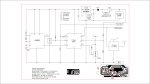
;Remote sensing and data transmission unit

;Humidity and temperature sensors using 08M2 to read HS1101 capacitive sensor and DS18B20's and output serial data at 1200 baud via a 433 MHz radio link
;data is transmitted ~ every 34.5 seconds as 8 bytes following a preamble and identifier text message
;unit can accept calibration during programming to get approximately +/- 3% accuracy from humidity sensor
;sensor capacitance varies from approximately 163 pF at 0% RH to about 201 pF at 100% RH
;555 circuit is similar to that used in HH10D module, but works at 5V.  Calibration factors work the same way
;temperature data is full 12 bits, rounded to nearest 0.1 deg C

#picaxe 08M2

symbol raw_humidity = w0			;b0, b1			
symbol raw_temperature = w1			;b2, b3			
symbol frequency_offset = w2			;b4, b5
symbol relative_humidity = w3			;b6, b7
symbol factor = w4				;b8, b9
symbol sensitivity = w5				;b10, b11			
symbol offset = w6				;b12, b13
symbol quotient = w7				;b14, b15


symbol remainder = b16
symbol sign1 = b17					
symbol whole_degrees1 = b18
symbol decimal_degrees1 = b19
symbol sign2 = b20
symbol whole_degrees2 = b21
symbol decimal_degrees2 = b22
symbol panel_voltage = b23


;Enter sensitivity and offset factors here from sensor calibration procedure
;offset is the measured RH sensor frequency at 0% RH obtained from testing in a dessicant chamber
;sensitivity is derived from the raw sensor value at 75.7% RH, using the formula (75.7 * 4096) / (0% RH frequency - 75.7% RH frequency)
;the sensor calibration spreadsheet, "Calibration factor calculation.xls" will derive the sensitivity factor.  Use commented out code below for calibration

	LET offset = 8112									;frequency for 0% RH
			
	LET sensitivity = 359								;derived from formula above (75.7% is RH above saturated sodium chloride paste at 20 deg C)

;Calibration can also be checked using saturated magnesium chloride paste, which should give 33.1% RH at 20 deg C	
;calibration chambers may take several hours at constant temperature for RH to stabilise.  Temperature must be held within +/- 1 deg C during calibration

;main programme loop
main:
;Read humidity	

	count c.3,1000,raw_humidity							;read raw humidity value
	
	frequency_offset = offset - raw_humidity					;subtract humidity frequency from 0% humidity frequency
	factor = frequency_offset / 16 + 1						;set a factor to reduce maximum value for rollover protection in next calculation		
	relative_humidity = 10 * frequency_offset / factor * sensitivity	;RH % x 10 for increased resolution
	
	factor = 4096 / factor								;factor back down from rollover protection
	relative_humidity = relative_humidity / factor
	
	quotient = relative_humidity / 10
	remainder = relative_humidity // 10						;remainder used for round up/down detection
	
			
	IF remainder >= 50 THEN LET relative_humidity = quotient + 1	;rounds up/down, gives rounded RH integer in % to nearest 1%
	ELSE LET relative_humidity = quotient
	ENDIF
	
	IF relative_humidity > 100 THEN LET relative_humidity = 100		;corrects for tiny resolution error that might give false over-reading
	ENDIF


;Read ground temperature	
	
	readtemp12 c.4,raw_temperature						;read raw ground temperature value
	
;convert 2's complement to decimal value and sign and round decimal degrees to nearest single decimal digit
;sets sign to ASCII 45 ("-") or space (" ", ASCII 32)
                              
  	LET sign1 = 32                                       			;set sign to ASCII 32 = " " (space character)
  	  	
  	IF raw_temperature > 64655 THEN                           		;-55 deg C = 64656
  	LET sign1 = 45                                       			;set sign to "-" for less than 0 deg C
	raw_temperature = - raw_temperature
	ENDIF                                
	
	whole_degrees1 = raw_temperature / 16
	decimal_degrees1 = raw_temperature * 4096 **10000 + 380 / 1000	;returns whole degrees as integer and decimal degrees as correctly rounded remainder to 0.1 deg C

;Read air temperature

	readtemp12 c.2,raw_temperature						;read raw air temperature value
	
;convert 2's complement to decimal value and sign and round decimal degrees to nearest single decimal digit
;sets sign to ASCII 45 ("-") or space (" ", ASCII 32)
                              
  	LET sign2 = 32                                       			;set sign to ASCII 32 = " " (space character)
  	  	
  	IF raw_temperature > 64655 THEN                           		;-55 deg C = 64656
  	LET sign2 = 45                                       			;set sign to "-" for less than 0 deg C
	raw_temperature = - raw_temperature
	ENDIF                                
	
	whole_degrees2 = raw_temperature / 16
	decimal_degrees2 = raw_temperature * 4096 **10000 + 380 / 1000	;returns whole degrees as integer and decimal degrees as correctly rounded remainder to 0.1 deg C
	

;Read solar panel voltage
	
	readadc c.1,panel_voltage							;~6.5 V = 1000 W/m² = 255 at ADC (100k + 30k divider)
	
	;255 = 6.5 V (5V), so 1 bit = 19.6 mV
	
		
;output data as binary as 8 bytes, preceded by a preamble, at 1200 baud, 8 bit, no parity, 1 stop bit with "OUT" identifier text at start of data
;sequence of 85's wakes up the receiver and sets zero point for signal 
;temperature, relative humidity and raw humidity value are transmitted as ASCII only for calibration purposes, as are CR and LF characters for terminal formatting

;data format is :
;sign1, whole_degrees1,decimal degrees1 is ground air temperature
;sign2,whole_degrees2,decimal_degrees2 is air temperature
;relative humidity
;panel voltage	
									
	setfreq m1
	
	sertxd (85,85,85,85,"OUT",sign1,whole_degrees1,decimal_degrees1,sign2,whole_degrees2,decimal_degrees2,relative_humidity,panel_voltage)
	
	;calibration code: 
	;sertxd (85,85,85,85,85,85,"OUT",sign1,whole_degrees1,decimal_degrees1,relative_humidity,#raw_humidity)

	setfreq m4
	
	SLEEP 1										;go to low power mode for ~2.3 secs							
	
	goto main										;loop back to start of programme


END
 

Jeremy Harris

Senior Member
As the above post got too long, here is the second half of this post:

The receiver just uses the receiver module connected to c.1 on an 08M2. The receiver also has a temperature sensor and humidity sensor (to measure room temp and humidity) and so it not only receives data from the RF link it also adds data from its own sensors. It then relays all the data to a separate data logger, via a three way cable that has power and a serial connection. This is the code that runs on the receiver:

Code:
;RF data link receiver at 433 MHz incorporating humidity and temperature sensors using 08M2 to read HS1101 capacitive sensor and DS18B20
;Receives RF data at 1200 baud and outputs serial data at 4800 baud
;unit can accept calibration during programming to get approximately +/- 3% accuracy from humidity sensor
;sensor capacitance varies from approximately 163 pF at 0% RH to about 201 pF at 100% RH
;555 circuit is similar to that used in HH10D module, but works at 5V.  Calibration factors work the same way
;temperature data is full 12 bits, rounded to nearest 0.1 deg C

#picaxe 08M2

symbol raw_humidity = w0			
symbol raw_temperature = w1			
symbol frequency_offset = w2
symbol relative_humidity = w3
symbol factor = w4
symbol sensitivity = w5				
symbol offset = w6
symbol quotient = w7

symbol remainder = b16
symbol sign = b17					
symbol whole_degrees = b18
symbol decimal_degrees = b19

symbol sign1 = b20
symbol whole_degrees1 = b21
symbol decimal_degrees1 = b22
symbol sign2 = b23
symbol whole_degrees2 = b24
symbol decimal_degrees2 = b25
symbol relative_humidity1 = b26
symbol panel_voltage = b27

symbol COM = 44


;Enter sensitivity and offset factors here from sensor calibration procedure
;offset is the measured RH sensor frequency at 0% RH obtained from testing in a dessicant chamber
;sensitivity is derived from the raw sensor value at 75.7% RH, using the formula (75.7 * 4096) / (0% RH frequency - 75.7% RH frequency)
;the sensor calibration spreadsheet, "Calibration factor calculation.xls" will derive the sensitivity factor.  Use commented out code below for calibration

	LET offset = 8312				;frequency for 0% RH
	
		
	LET sensitivity = 355				;derived from formula above (75.7% is RH above saturated sodium chloride paste at 20 deg C)

;Calibration can also be checked using saturated magnesium chloride paste, which should give 33.1% RH at 20 deg C	
;calibration chambers may take several hours at constant temperature for RH to stabilise.  Temperature must be held within +/- 1 deg C during calibration

;main programme loop
main:
	
	;get data from 433 MHz radio link receiver
	;data format is:
	;air temperature, ground temperature, relative humidity, solar panel voltage
	
	serin c.1,N1200_4,("OUT"),sign1,whole_degrees1,decimal_degrees1,sign2,whole_degrees2,decimal_degrees2,relative_humidity1,panel_voltage
	
	count c.3,1000,raw_humidity
	readtemp12 c.2,raw_temperature						;read raw humidity and temperature values
		
	GOSUB convert									;temperature conversion sub-routine returns sign, integer degrees and single decimal place ASCII character
	
	frequency_offset = offset - raw_humidity					;subtract humidity frequency from 0% humidity frequency
	factor = frequency_offset / 16 + 1						;set a factor to reduce maximum value for rollover protection in next calculation		
	relative_humidity = 10 * frequency_offset / factor * sensitivity	;RH % x 10 for increased resolution
	
	factor = 4096 / factor								;factor back down from rollover protection
	relative_humidity = relative_humidity / factor
	
	quotient = relative_humidity / 10
	remainder = relative_humidity // 10						;remainder used for round up/down detection
	
			
	IF remainder >= 50 THEN LET relative_humidity = quotient + 1	;rounds up/down, gives rounded RH integer in % to nearest 1%
	ELSE LET relative_humidity = quotient
	ENDIF
	
	IF relative_humidity > 100 THEN LET relative_humidity = 100		;corrects for tiny resolution error that might give false over-reading
	ENDIF
	
	
	;output temperature and relative humidity data at 4800 baud, 8 bit, no parity, 1 stop bit with "T"as start of string character
	
	sertxd ("T",sign,whole_degrees,decimal_degrees,relative_humidity,sign1,whole_degrees1,decimal_degrees1,sign2,whole_degrees2,decimal_degrees2,relative_humidity1,panel_voltage,CR,LF)
	
	;Transmitted data format is:
	
	;room temperature (sign, whole, decimal), room RH, ground temperature (sign, whole, decimal), air temperature (sign, whole, decimal), outside RH, panel voltage
	
	
	;NOTE:  No delay in loop as code above takes about 3 seconds or so to execute	if a regular redio data burst is being received						
	goto main										;loop back to start of programme


;convert 2's complement to decimal value and sign and round decimal degrees to nearest single decimal digit
;sets sign to ASCII 45 ("-") or space (" ", ASCII 32)
convert:
                              
  	LET sign = 32                                       			;set sign to ASCII 32 = " " (space character)
  	  	
  	IF raw_temperature > 64655 THEN                           		;-55 deg C = 64656
  	LET sign = 45                                       			;set sign to "-" for less than 0 deg C
	raw_temperature = - raw_temperature
	ENDIF                                
	
	whole_degrees = raw_temperature / 16
	decimal_degrees = raw_temperature * 4096 **10000 + 380 / 1000	;returns whole degrees as integer and decimal degrees as correctly rounded remainder to 0.1 deg C

	RETURN

	
END
 
Top