short mechanical switch

Hello Forum.
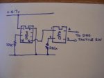
I have a dds sine wave generator which I would like to switch on via one of it's tactile push button swithes remotely via my 08M picaxe microprossesor. I have done this with my 08M and an optocoupler and a hacked digital camera on/off switch before, but it won't work for my dds generator for some unknown reason now.I have my 08m2 picaxe chip optocoupler and npn transisters waiting, but am unsure how to do it. Can anyone point me to a web site that explains how to do it, or could a member possibly post a simple circuit diagram to help me? Thanks.

David miles.
 

Reloadron

Senior Member
Can you post the existing circuit you are trying to use which won't work? Also, if you use the picaxe to drive an optocoupler why the need for an additional NPN transistor? Have you measured across the tactile switch to see exactly what is being switched?

Ron
 
Can you post the existing circuit you are trying to use which won't work? Also, if you use the picaxe to drive an optocoupler why the need for an additional NPN transistor? Have you measured across the tactile switch to see exactly what is being switched?

Ron
I only mentioned the npn to say that I am not short of electronic gear in my parts box if need be. The tactile switch on my DDS generator that I have hard wired two wires to measures 5volts normally and zero volts when pressed ( on )

I hope that I have attached circuit diagram to this message!.

DavidDDS 08m.JPG
 

srnet

Senior Member
Put a voltmeter across the tactile switch, without the PICAXE circuit connected.

What happens to the voltage when the switch is pressed ?

Now connect the PICAXE Circuit.

What happens to the voltage now, when the PICAXE tries to control the switch ?
 

hippy

Ex-Staff (retired)
If all else fails you can connect a relay contact across the switch, then switch the relay to simulate pressing the button. That way it doesn't matter what circuit there is on the DDS Generator side of things.
 
Put a voltmeter across the tactile switch, without the PICAXE circuit connected.

What happens to the voltage when the switch is pressed ?

It goes from 4.7v to zero volts
-----------------------------
Now connect the PICAXE Circuit.

What happens to the voltage now, when the PICAXE tries to control the switch ?
It stays at 4.7v
---------------
I have added an LED from picaxe pin 2 to ground and it switches on and off as per code.
-----------------------------------------------------------------------------------
David.
 
And what happens at pin 2 of the opto coupler ?

Not easy to see, but 4.5v between pin 2 and ground when led is off and flickers between 2.6v and 3.7v when led is on.
------------------------------------------------------------------------------------------------------------------
David
 

rq3

Senior Member
And what happens at pin 2 of the opto coupler ?

Not easy to see, but 4.5v between pin 2 and ground when led is off and flickers between 2.6v and 3.7v when led is on.
------------------------------------------------------------------------------------------------------------------
David
Well, (not for the first time), I'm very confused!
1) Are you trying to DUPLICATE the function of the switch with the Picaxe and optocoupler (i.e., parallel the optocoupler with the switch?).
2) What does the DDS (direct digital synthesizer?) EXPECT to see when the switch is pressed? A grounded pin?
3) Pins 1 and 2 of the optocoupler are connected to an INTERNAL LED in the optocoupler. When the Opto is ON (Pin 1 high), you will measure the forward voltage of the internal LED and the external 220 ohm resistor (probably somewhere around 3.5 volts).
4) There is a NPN phototransistor inside of the opto (probably), with its emitter connected to pin 3, and its collector connected to pin 4 (probably, hard to tell without the opto datasheet).
5) Completely disconnect the opto from your switch and DDS. Connect a 10K or so resistor (pull-up) between the opto pin 4 and +4.7V. Connect the opto pin 3 to ground. Now run your Picaxe routine and measure between opto pin 4 and ground. What do you see? IF all of the above dangerous assumptions are true, you should see opto pin 4 read about +0.7V for 1 second, and then +4.7V for 5 seconds. (I'm assuming High 2 in your code means physical pin 5 on the 08M gets a high output).

Rip
 

Reloadron

Senior Member
I only mentioned the npn to say that I am not short of electronic gear in my parts box if need be. The tactile switch on my DDS generator that I have hard wired two wires to measures 5volts normally and zero volts when pressed ( on )

I hope that I have attached circuit diagram to this message!.

DavidView attachment 18295
I would just place a NPN switching transistor like a 2N2222 or 2N3904 (just about any low power NPN switching transistor across the tactile switch with Collector to the +5 volt side and Emitter to the 0 volt side. Try around a 2.2K base resistor from the PICAXE. You aren't switching any current to speak of really. If a 2.2 K base resistor won't work then try a 1 K. That is how I would approach it anyway.

Ron
 
Last edited:
Top