Hi there!
As some of you may know, I've been making a set of board for a remotely operated set of mains sockets for a college project.
So far I have:
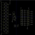
Made the relay board with a TPIC6C595 shift register
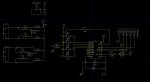
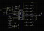
Made the top and bottom controller boards including 6 button ADC control, IR control and PICAXE interface with download socket, LED's indicating socket status etc.
To date I have:
Managed to get the 6 button ADC working including matching LED for each button.
gotten the PWM LED duty to work with the Socket LED's that when sockets(relays)/LED's are ALL off, the PWM LED dims. When 1 or more socket(relay) is on, the matching LED is also on, and the PWM LED is bright.
Now, I have interfaced the controller board to the relay board and using the SPI bus, gotten the controller board to work the relays.
i.e. when button 1 is pressed, relay 1 turns on, when button 2 is pressed, relay 2, turns on. When button 5 is pressed, the relays that are currently on turn off, when button 5 is pressed again, relays 1 and 2 that were previously on but now off, turn on again.
Simply put, it works very well to my liking and also to my design specification although I haven't tested the IR interface.
All that aside, the issue im having now is that when power is applied to the circuit as a whole, the shift register for some reason turns ALL of the relays on even though there is no code in the picaxe for it to do that.
If there's no power to the PICAXE and power is applied, the relays do nothing.
If I include right at the very beginning of the code to write 0's into the shift register, when power is applied and the picaxe powers up, the relays turn ON, and then OFF because the code tells it too.
All I can think is that there is something that the picaxe is doing when it first starts up that's turning on the relays, any idea?
As some of you may know, I've been making a set of board for a remotely operated set of mains sockets for a college project.
So far I have:
Made the relay board with a TPIC6C595 shift register
Made the top and bottom controller boards including 6 button ADC control, IR control and PICAXE interface with download socket, LED's indicating socket status etc.
To date I have:
Managed to get the 6 button ADC working including matching LED for each button.
gotten the PWM LED duty to work with the Socket LED's that when sockets(relays)/LED's are ALL off, the PWM LED dims. When 1 or more socket(relay) is on, the matching LED is also on, and the PWM LED is bright.
Now, I have interfaced the controller board to the relay board and using the SPI bus, gotten the controller board to work the relays.
i.e. when button 1 is pressed, relay 1 turns on, when button 2 is pressed, relay 2, turns on. When button 5 is pressed, the relays that are currently on turn off, when button 5 is pressed again, relays 1 and 2 that were previously on but now off, turn on again.
Simply put, it works very well to my liking and also to my design specification although I haven't tested the IR interface.
All that aside, the issue im having now is that when power is applied to the circuit as a whole, the shift register for some reason turns ALL of the relays on even though there is no code in the picaxe for it to do that.
If there's no power to the PICAXE and power is applied, the relays do nothing.
If I include right at the very beginning of the code to write 0's into the shift register, when power is applied and the picaxe powers up, the relays turn ON, and then OFF because the code tells it too.
All I can think is that there is something that the picaxe is doing when it first starts up that's turning on the relays, any idea?
Code:
;Remotely controlled sockets program, written by Nigel Nichols

gosub shift 		' to turn relays off because the relays turn on upon boot

symbol MOSI = B.2		' pinouts to the relay board
symbol SRCK = B.1
symbol RCK = B.0

symbol counter = b7	' variable used during loop
symbol var_out = B0	' data variable used during shift
symbol bits = 8		' number of bits

symbol dataout = B0	' data to transmit
symbol Buttons = B3	' variable used to hold button ADC value
symbol PortBstatus = B4	' variable used to hold port status in order to turn all on/off
symbol latch = B5		' variable used to hold port status when 'current on/off' button used
pwmout B.3, 63, 10	' PWM to control status LED

main:
debug
let latch = portBstatus ' copies the portBstatus into latch
if pinsB >14 then pwmduty B.3,255 	' If there is an LED/Relay on, the status LED will be bright, else dim
else pwmduty B.3,10
endif
Readadc c.2,buttons	' Forces a check of the button ADC
if buttons >10 then gosub buttonstatus	'If a button is pressed it will be greater than 1
goto main

Buttonstatus:
Readadc c.2,buttons	' Double checks the button that is pressed as a minor debounce
if buttons >240 then gosub socket1
if buttons <240 and buttons >200 then gosub socket2
if buttons <200 and buttons >160 then gosub socket3
if buttons <160 and buttons >100 then gosub socket4
if buttons <100 and buttons >50 then gosub Current
if buttons <50 and buttons >10 then gosub All
return

Socket1:
If pinb.4 = 0 then high b.4 	' this acts as a latch, if the LED is on, then it'll
else pinb.4 = 0			' turn off, if it's off then it will be on
endif
gosub shift				' before the pause but after the selection is made
pause 100				' this will shiftout
return
Socket2:
If pinb.5 = 0 then high b.5
else pinb.5 = 0
endif
gosub shift
pause 100
return
Socket3:
If pinb.6 = 0 then high b.6
else pinb.6 = 0
endif
gosub shift
pause 100
return
Socket4:
If pinb.7 = 0 then high b.7
else pinb.7 = 0
endif
gosub shift
pause 100
return
Current:
let PortBstatus = outpinsB
if portbstatus > %00001000 then let pinsB = %00001000 gosub shift return
else let pinsB = latch	' %00001000 is used to keep the PWM out enabled
endif
gosub shift
pause 100
return
All:
let PortBstatus = outpinsB
if portbstatus > %00001000 then let pinsB = %00001000 gosub shift return
else let pinsB = %11111000 'turns all relays on/off and whatever is on, off also
endif
gosub shift
pause 100
return

shift:
let dataout = outpinsB
dataout = dataout / 16
	for counter = 1 to bits
		if bit7 = 1 then   	' as data if shifted, if its a 1 it stays high, else goes low
			high MOSI
		else
			low MOSI
		endif
		pulsout SRCK,1 		' pulse clockpin for 10us
		var_out = var_out * 2 		' shift variable left for MSB
	next counter
	pulsout RCK,1
return") ) of late to sort the code out but I will look into it.
) of late to sort the code out but I will look into it.