I've built another ebike based on this design:

 www.instructables.com
However I've used a pair of brushless motors recycled from electric drills. I am also reusing the control electronics. The speed of the motors is controlled by a 0 to 5V signal from the drill trigger switch. It was the switch mechanism that died in each drill.
www.instructables.com
However I've used a pair of brushless motors recycled from electric drills. I am also reusing the control electronics. The speed of the motors is controlled by a 0 to 5V signal from the drill trigger switch. It was the switch mechanism that died in each drill.
I wanted to control the motors using high/low/stop micro-swiches mounted on the bike handlebars.
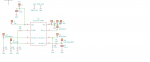
My design uses a picaxe to output a pwm signal whose duty cycle is controlled by the micro-switches. The pwm signal goes to a RC digital analog converter based on the information based at this page:
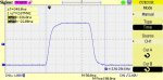
Seems easy enough. For example, if I used a 10K and 100nF combination with a 40kHz pwm signal at 50% duty cycle, I get about 2.5V out.
The pwmduty command uses a 0-1023 variable in its syntax. I assumed that if I used:
pwmduty c.2, 510
I would get roughly a 50% duty cycle and therefore 2.5V output from the picaxe DAC
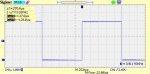
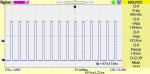
However, there seemed to be no relationship between the variable used, in my example 510, in the pwmduty command and the output voltage. I ended up finding the values to use in the pwmduty command by trial and error.
What is the relationship between the variable used in the pwmduty command and the output duty cycle? If I use a quarter of 1023 (ie about 250), should I get a 25% duty cycle?
Thanks.
Friction Drive Build for Bikes
Friction Drive Build for Bikes: Friction drive build for bikes Hello to all, I decided to build this friction drive system for my hybrid mountain bike(Carrera Vulcan disc spec) earlier this year to essentially aid me up a hill(average grade 4%) on the journey home from work. I had…
www.instructables.com
I wanted to control the motors using high/low/stop micro-swiches mounted on the bike handlebars.
My design uses a picaxe to output a pwm signal whose duty cycle is controlled by the micro-switches. The pwm signal goes to a RC digital analog converter based on the information based at this page:
Seems easy enough. For example, if I used a 10K and 100nF combination with a 40kHz pwm signal at 50% duty cycle, I get about 2.5V out.
The pwmduty command uses a 0-1023 variable in its syntax. I assumed that if I used:
pwmduty c.2, 510
I would get roughly a 50% duty cycle and therefore 2.5V output from the picaxe DAC
However, there seemed to be no relationship between the variable used, in my example 510, in the pwmduty command and the output voltage. I ended up finding the values to use in the pwmduty command by trial and error.
What is the relationship between the variable used in the pwmduty command and the output duty cycle? If I use a quarter of 1023 (ie about 250), should I get a 25% duty cycle?
Thanks.
Code:
#no_data

pwmout C.2,24, 0          ;make sure c.2 DAC voltage is zero
                 ;must have pwmout before main program
w0=30

main:

if pinC.1=1 then         ;c.1 connected as a kill switch.
   pwmduty c.2, 0         ;sets duty cycle to 0%
   w0=30
   goto main
endif

if pinC.3=1 then         ;c.3 increase speed switch
    goto increase_speed
endif

if pinC.4=1 then         ;C.4 decrease speed switch
    goto decrease_speed
endif
goto main

increase_speed:
pwmduty c.2, w0
w0=w0+10 max 70        ;max 3.5V by trial and error
pause 500             ; else it goes straight to 3.5V without pause
goto main

decrease_speed:
if w0<30 then main     ;sets min DAC at 1.5V
w0=w0-10 min 30
pwmduty c.2, w0
pause 500
goto main