Servo/Servopos mystery

PhilipS

New Member
gosub PROBLEM SOLVED

a) I have read the Read Me First document
b) I have searched the forums and found nothing
c) This is a 'hobby', I have little electronics experience, this is my first PICAXE, but I do have software experience.

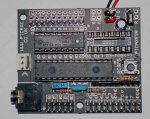
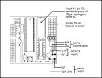
I recently received my Picaxe 28x1 and the servo upgrade pack. I followed the instructions given with the servo pack, i.e. soldered on the 10 way header, fitted the DIL resistor pack and connected the supplied 6V battery pack to header E and then connected the servo to output 0.

Using the program on the instruction sheet supplied with the servo upgrade (modified the 'loop' label as that's a reserved word) the servo rotates clockwise and then buzzes. I tried the example program in picaxe_manual3.pdf and that behaves the same.

I changed the program to use different output ports, still no joy.

At this point I was thinking the servo must be broken; however I found code someplace that used pulsout and when I tried that it worked just fine which makes me think that the servo is ok but the servo/servopos commands aren't working.

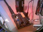
I don't have any spare bits I can swap out and I don't have much in the way of diagnostic equipment - a multi-meter and some LEDs. I patched the outputs into a breadboard and connected LEDs to show Power, Output 0 (and Output 7 so I could flash the LED to show what the program was up to) and patched up to a header for the servo with signal from output 0, V2+ and 0V.

The power to the picaxe (from 3 alkaline cells) is 4.42V

I can measure 5.81V coming from the board to the servo header (4 x alkaline).
When I use the pulsout command I can see LED0 light up, the brightness dependent on the width of the pulse (which is what I would have expected) and the servo rotates anti-clockwise as expected.

When I use the servo or serverpos commands LED0 remains unlit (or very, very dim I suppose) and the servo rotates fully clockwise and then buzzes. I have tried to measure the voltage on the signal pin, it read as 0.009/0.010 when the servo/servopos commands were executing, and 0.000 when the program finished. I wouldn't like to say how accurate or meaningful those measurements are as waving the leads about can give a higher reading.

I'm using the command line compiler on Linux which reports "PASS - programmed PICAXE-28X1 (40X1) vA.4 successfully.". (The program seems just fine other than not seeing the board sometimes and other programs I have written all seem to operate correctly, e.g. I have successfully connected up an SRF005 (using port 0), switches and LEDs )

Here is the program I have been using - nothing complicated - any ideas on what might be wrong?

Code:
symbol servopin = 0
low 7
b0 = 75 : gosub pulseto
b0 = 150 : gosub pulseto
b0 = 225 : gosub pulseto

high 7
gosub example1
gosub example2

low 7
pause 2000
end

' This is the example given on the servo upgrade pack instruction sheet
example1:    servo 0,75
   pause 2000
   servo 0,150
   pause 2000
   servo 0,225
   pause 2000
   return

' This is the example given in picaxe_manual3.pdf
' but changed to use port '0' instead of '4'
example2: servo 0,255 ' start servo on 4
pause 2000
main: servopos 0,75 ' move servo to one end
pause 2000 ' wait 2 seconds
servopos 0,150 ' move servo to centre
pause 2000 ' wait 2 seconds
servopos 0,225 ' move servo to other end
pause 2000 ' wait 2 seconds
return


pulseto:
   for b1 = 1 to 20
       pulsout servopin, b0
       pause 20
   next
   return
===========
PROBLEM SOLVED:

Rev-ed shipped me a new chip with V A.5 of the firmware and the servo/servopos commands work just fine

Thanks everyone
===========
 
Last edited:

BeanieBots

Moderator
Wow, what a beautifully presented question.
So refreshing.

Everything sounds OK except your pulsout routine.
You're sending pulses in the range 1 to 20 which are way too short.
The values sent by pulsout should be in the same range as if you were servo.
Did you say that bit worked?

Please try this and let me know the results:

main:
for b0=1 to 100
pulsout 0,130
pause 20
next b0

for b0=1 to 100
pulsout 0,170
pause 20
next b0
goto main
 

PhilipS

New Member
Your program works too.

The pulseout is the only part that does work (which is why I think the servo is ok). My code should be sending pulseout the correct values as I pass in

b0 = 75 : gosub pulseto
b0 = 150 : gosub pulseto
b0 = 225 : gosub pulseto

which are the rightmost, middle and leftmost positions (if the documentation is correct)
 

BeanieBots

Moderator
Sorry, my mistake. I miss-read your b0 as being the variable you were using in the for/next loop. (b1).

OK, what about this:- Just humour me;)

main:
servo 0,130
pause 2000
servo 0,170
pause 2000
goto main
 

BeanieBots

Moderator
Oh dear:confused:
I'm afraid it sounds like a dodgey 28X1.
I don't a V4 to try only V3.
Interestingly, the latest change was to do with servo!
This is one for Technical.

Might be worth trying the same program on all pins just to make sure it's not pin related and give technical some more clues to work with.
Sorry, can't help any further.
 

PhilipS

New Member
I have done more testing

Using LEDs on 5,6,7 to indicate left/middle/right position requested I tested 0,1,2,3 and 4 for servo output. None of the servo/servpos commands worked.

Some might find it strange (i know I do) but iff, when I am driving a servo on a port other than 0, I issue an erroneous servo command for the previous port (i.e. servo 0, 225 when I have the servo on port 1) before I try to move the servo on the proper port the servo commands work:eek:! In addition some 12 seconds after the program ended, the servo port output comes back on and stays on for quite some time (more than 2 minutes)

Hopefully that should be enough information for someone to get a handle on the problem.

My final code is here

Code:
symbol servopin = 4

	high 5
	b0 = 75 : gosub pulseto
	pause 2000
	low 5 : high 6
	b0 = 150 : gosub pulseto
	pause 2000
	low 6 : high 7
	b0 = 225 : gosub pulseto
	pause 2000
	low 7
	gosub example1
	gosub example2

end

' This is the example given on the servo upgrade pack instruction sheet
example1:
	servo 3,225		' This is magic
	high 5
	servo servopin,75
	pause 2000
	low 5 : high 6
	servo servopin,150
	pause 2000
	low 6 : high 7
	servo servopin,225
	pause 2000
	low 7
	return

' This is the example given in picaxe_manual3.pdf
example2:
	servo servopin,75 ' start servo 
main:
	high 5
	servopos servopin,75 ' move servo to one end
	pause 2000 ' wait 2 seconds
	low 5 : high 6
	servopos servopin,150 ' move servo to centre
	pause 2000 ' wait 2 seconds
	servopos servopin,225 ' move servo to other end
	low 6 : high 7
	pause 2000 ' wait 2 seconds
	low 7
	return


pulseto:
	for b1 = 1 to 20
		pulsout servopin, b0
		pause 20
	next
	return
Do I need to throw the toys out of the pram to get someone to look into this?;)
 

BeanieBots

Moderator
Well theoretically, you won't get an "official" response until we are back into "office hours". Rev-Ed is not 24/7 but they often work late so you never know.
It certainly is very odd behaviour. The sort of thing which might happen if either serin or reset were left floating.
Might be worth having a good look at the board to see if that is the case.

Meanwhile, give this a go:

main:
servo 0,150
do
servopos 0,130
pause 2000
servopos 0,170
pause 2000
loop

Any change in the behaviour?
 

eclectic

Moderator
"Hopefully that should be enough information
for someone to get a handle on the problem."

Keep the toys in, for the time being. :)

Which board are you using?
Are ALL unused inputs grounded?
Single or twin power supply (ies)?
Anything else connected, besides servo and LED/res ?

e
 
Last edited:

PhilipS

New Member
Just tried that and it just rotates clockwise and quivers.

Edit: And, assuming that pin 6 is SerIn and pin 1 is reset, as far as I can see using a magnifying glass, it is all soldered as expected.
 
Last edited:

PhilipS

New Member
Which board are you using?

The board in the 28x1 starter pack - which I presume is the same as the 28X1 dev board.

Are ALL unused inputs grounded?

This is a standard board that has one of those long thin resistor things installed - so I assume so.

Single or twin power supply (ies)?

As I said in the original post, I am using the battery pack that came with the servo upgrade and it is connected to header E. As part of my testing I did try and use a single supply but suffered from the same problem, therefore switched back to the recommended two battery solution.


Anything else connected, besides servo and LED/res ?

When I first had the problem, nothing was connected - I was connecting the servo directly to the pins on the board. Now there is nothing other than LED/resistors. I can't easily provide a photo but all there is is a single row header pushed into the breadboard, connected to the board using the ribbon cable supplied with the start pack to which I have added another 20pin IDC socket. This connects to a 10 LED thing (like you would use for a bar graph display) with 330R resistors to the 0 bus (from pin 1 on the cable). All the connections work fine as I can switch all the LEDs on or off at will.
 

PhilipS

New Member
I could humour you by saying as it's your board it isn't on it, but on my board it *was* on the three pins 'sideways' where the 0 is. - but you only have two pins on your board. The connector was oriented with the control wire (white) on the pin nearest to the resistor pack (which replaces the darlington array fitted in your board).

I see I might have to work out how to get a picture of my board at this rate, but I'm pretty sure that the connections are correct because the servo always works using pulsout commands.
 

PhilipS

New Member
Yep - that's the same as the diagram in the installation instructions and is how it was originally configured (and didn't work). I have tried other ports without any success using the example programs given. I have a crappy mobile phone picture of the board . Yep it's pretty crappy and not much use.
 

Attachments

Last edited:

tarzan

Senior Member
PhilipS

Are you using four AA batteries to power the Picaxe?

If your Picaxe suppy Voltage is much above 5V then this could be the cause of your problems. Recommend only three AA batteries for Picaxe supply and four AA batteries for servo.
 

PhilipS

New Member
I am using the 3 battery box that came with the starter pack for the Picaxe, and the 4 battery box that came with the servo upgrade with the servo.

I patched the outputs into a breadboard and connected LEDs to show Power, Output 0 (and Output 7 so I could flash the LED to show what the program was up to) and patched up to a header for the servo with signal from output 0, V2+ and 0V.

The power to the picaxe (from 3 alkaline cells) is 4.42V

I can measure 5.81V coming from the board to the servo header (4 x alkaline).
 

westaust55

Moderator
PhilipS,

in the program in your first post, I spotted the lines:
Code:
example2: servo 0,[B]255[/B] ' start servo on 4
pause 2000

I have not used servo's myself but my understanding is that the value of 255 would be trying force the servo too far and hence give the chattering you might have been hearing. Also believe that excessive travel can damage the servo.

I do note that this line is removed in later posts
 
Last edited:

PhilipS

New Member
Well spotted - my fingers are too fat to type!

I asure you that I have tried so many different programs and variations thereof that I know that this command will have been ignored - the servo always goes all 'the other way', i.e. clockwise towards the zero end of the scale, and buzzes.

I originally thought the problem was my ineptitude (first Picaxe, first servo, first program) but there seems to be some fundamental problem with my system. Hopefully Technical can cast some light on this and I can get back to playing.
 

barlow

New Member
Jitter

I don't know if this is relevant. I have an older 18X and when controlling servos using the Servo command I find that Serout and Gosub commands cause jitter in the servo. Why Gosub does this I have no idea. I assume Serout affects the internal timer/timing somehow.
 

alpacaman

Member
Yep - that's the same as the diagram in the installation instructions and is how it was originally configured (and didn't work). I have tried other ports without any success using the example programs given. I have a crappy mobile phone picture of the board . Yep it's pretty crappy and not much use.
I noticed that your programming cable is plugged in. Are you leaving the programming cable plugged in? If so, unplug it and see what happens.

I've been told that this shouldn't matter. However, I have built a couple dozen PICAXE projects, many with servos, and I've always had to unplug the programming cable to get any of them to work.

Please no replys about this - we've been through all the steps before (reset pin, supply voltage, decoupling caps, etc...).
 

BeanieBots

Moderator
I noticed that your programming cable is plugged in. Are you leaving the programming cable plugged in? If so, unplug it and see what happens.

I've been told that this shouldn't matter. However, I have built a couple dozen PICAXE projects, many with servos, and I've always had to unplug the programming cable to get any of them to work.

Please no replys about this - we've been through all the steps before (reset pin, supply voltage, decoupling caps, etc...).
I know you didn't want any replies, but you clearly have a problem.
Valid to point your issue out, as there may be a common problem.
However, servos should (and do) work with or without the lead plugged in.
I've made dozens of PICAXE/servo circuits. (08M,18X,28A,28X & 28X1). All worked with/without lead for both serial and USB type.
 

alpacaman

Member
I know you didn't want any replies, but you clearly have a problem.
Valid to point your issue out, as there may be a common problem.
However, servos should (and do) work with or without the lead plugged in.
I've made dozens of PICAXE/servo circuits. (08M,18X,28A,28X & 28X1). All worked with/without lead for both serial and USB type.
I have the problem with or without circuits which are using a servo.
It does it with boards I've built and with the dev boards Rev-Ed has built. I'm using a serial cable and I'm not going to spend the money on a USB cable just to see if that fixes it. The serial cable, from Rev-Ed, should work. I've tried it on 2 different computers running windows XP. It doesn't matter what version the edit software is and I tested the cable, and serial port, using the test serial port function of the software. It does it with regulated power supplies and with batteries. Since it does it regardless of who made the circuit board, me or Rev-Ed, I don't think it's a circuit problem.
I've never had a problem programming the chips and all the projects I've built, have been reliable. After programming the chip tries to run the program and, the best I can tell, it may make it though the loop one time and then stops. The only time I've been successful in running the program with the cable plugged in is when I'm using the SERTXD command.

The only thing I can think of is something I'm doing wrong in each and every one of my programs - regardless of how simplw or complex. A simple program to blink an LED right out of PICAXE manual 1 doesn't work.

I've gone though this on the forum before and I've tried everything suggested, except buying a USB cable, and nothing has worked.
 

BeanieBots

Moderator
All I can say is "most odd".
Doesn't happen to anyone else (except when serin or the like is left floating).
You've tried two machines, but they both have something in common. They both belong to you. It might be some 'strange' software you have on both machines. Perhaps something that polls the serial port making the PICAXE think it is about to start a download.
Maybe try on somebody elses machine.

If you have a DSO, hang it on the serin pin and have look for 'oddities'.
 
Last edited:
Top