SeanHowson
Member
Hi
so ive recently spent a while playing aroud with a 20*4 OLED screen, so im fairly well practiced with the serout command but im having a little trouble getting the serin command to work with my prototyping gear, at the moment im using a 40X2 (with protoboard) and a 28X2 (and project board), (all my components are the ones available on the picaxe website). Both boards are running off a 4.5v power supply in parrallel
i have a single wire connecting the two boards going between my chosen input and output, the power cables, besides that, the only other wires on the boards are bridging wires that ground any unused inputs, (this posed an issue with the other project the 40X2 board is used for, the project i mentioned using the OLED screen, i had huge issues with static interference)
the codes im currently using are as follows:
40x2:
28X2 code:
all i want to do is have the 40X2 respond to a serial output from the 28X2
any help would be appriciated
many thanks
Sean
so ive recently spent a while playing aroud with a 20*4 OLED screen, so im fairly well practiced with the serout command but im having a little trouble getting the serin command to work with my prototyping gear, at the moment im using a 40X2 (with protoboard) and a 28X2 (and project board), (all my components are the ones available on the picaxe website). Both boards are running off a 4.5v power supply in parrallel
i have a single wire connecting the two boards going between my chosen input and output, the power cables, besides that, the only other wires on the boards are bridging wires that ground any unused inputs, (this posed an issue with the other project the 40X2 board is used for, the project i mentioned using the OLED screen, i had huge issues with static interference)
the codes im currently using are as follows:
40x2:
Code:
#PICAXE 40X2

main:
serin A.0,N2400,b0 ; assign data to variable
if b0 = 60 then
high B.6
wait 60              ;1 minute to get the multi meter onto output b.6 and see if the data was received
low b.6
end if
low b.6             ;

goto main
Code:
#PICAXE 28X2

main:
high b.1                          ;test output to make sure the chip/board is funtional
serout B.3,N2400,(60)
goto mainany help would be appriciated
many thanks
Sean
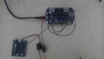
") might just be how you phrased the questioned, the wire connecting the two chips, is soldered at each end onto the input/output pad on the PCB given, i'll post a picture up in a second (please ignore the screen and grounding wires etc)
might just be how you phrased the questioned, the wire connecting the two chips, is soldered at each end onto the input/output pad on the PCB given, i'll post a picture up in a second (please ignore the screen and grounding wires etc)