"SerialPower" true two-wire data+power network

kranenborg

Senior Member
The Picaxe "SerialPower" Network combines power delivery and bi-directional communications between processes on intelligent nodes using just two interchangeable wires. In this way, an advanced distributed processing system (based on Picaxe nodes) can be built easily:


This network is based on two - independent - concepts:
- Networking hardware for linking Picaxe-based nodes transmitting power and data over two non-polarized lines
- Picaxe network software that implements communicating processes on a multi-drop network

A master node provides for power as well as "timeslots" during which processes on nodes can exchange messages with each other using a standard format. The slave nodes are powered from the network and only need a backup capacitor. Both master and slave nodes can be implemented using any available Picaxe type.

The concept of communicating processes is used (each process has a unique identifier), allowing abstraction from physical nodes and thereby flexible distribution of functionality over different nodes. A node may implement several processes, and the same process may run concurrently on several nodes with local modifications, as shown in the figure below (temperature reading process #11 adresses display process #2 which is distributed over two nodes);
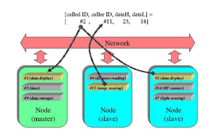


The master node is completely application-independent, any process on a node can exchange information with any process on another node (including slave-slave comms). Message collissions are avoided by assigning each sending process a separate ID-marked timeslot. After network power-up, the master node automatically roams the network for processes that may want to send messages and stores the corresponding process IDs for automatic timeslot generation later on. Furthermore, processes can register or remove timeslots for other processes on the fly as well.

The network software can be configured to use simple three-wire "diode-mixing" networks with separate power and serial communication lines as well, the hardware description page tells more about these options

All information (template code, examples, architecture document, hardware description etc.) can be found through the following up-to-date link:
SerialPower I & II (https://www.kranenborg.org/ee/picaxe/twowirenetwork.htm)

Currently supported versions:
  • SerialPower I: V4.0 (for Picaxe M2 and/or X2 variants), fixed-length (2 byte) messages (September 2018)
  • SerialPower II (for Picaxe M2 and/or X2) with variable length messages ranging from 1 to 32 bytes (November 2022)
Both versions are actively maintained. SerialPower I is useful for sensor-oriented networks, SerialPower II is intended for more complex networks where different types of information are distributed.

Regards,
Jurjen Kranenborg
 
Last edited:

kranenborg

Senior Member
Update "SerialPower" Version 2.0 (Sept. 2007)

Hello,

I have significantly upgraded the functionality, software and documentation and it now (v2.0) supports the following:

  • Fully automatic registration and provision of timeslots for up to 48 sending slave processes
  • On-the-fly registration or removal of new timeslots (e.g because of some sensor condition or tripped switch)
  • Plug & Play slave node support (including dynamic process ID assignment)
  • Application of simple, "diode mixing" network hardware where separate power and communication lines are used.
  • Support for Network Manager Node for automatic removal of unused timeslots and on-the-fly message CRC checking,
  • User Guide for application programming

The link to the updated website is in the first post of this thread.


In more detail the updates imply the following:

Software (Network stacks for master and slave nodes)

Intelligent network-roaming master node + auto-registering slaves:

The master node now implements the following system processes:
- registerSendingprocess (request timeslots for a particular process)
- unRegisterSendingprocess (stop generating timeslots for a particular process)
- flashLEDmasterNode
It calls the following slave processes:
- roamSendingProcess (search network for sending processes; allow them to register in response)
- roamPlugNplayNode (allowing a plug & play node to get network access by registering extra timeslots)
- availableTimeSlot (make a timeslot available to a certain process, allowing it to send a message)
- configNetworkManager (if Network Manager node is in the system)

After power-up, the master node now automatically searches for potentially sending process IDs on the network (calling the "roamSendingProcess" process on slaves). The slave nodes *automatically* respond by registering timeslots for the IDs of any sending processes they implement (using "registerSendingProcess"). Consequently, the master node has become completely application independent and need not be reprogrammed for a new application, greatly simplifying application programming. All registered IDs are stored and managed in the 48-byte RAM memory of the PICAXE (all master node code still fits in a 08M!).

The master node now also has an indicator led that flashes very shortly whenever a slave node message has been received and decoded. Thus a simple but effective indicator of network activity is available. This indicator may also be addressed explicitly by any slave proceses using the above mentioned "flashLEDmasterNode" process with light duration as a parameter.

More advanced, big applications can now use sending slave processes that may request timeslots for other processes as well on the fly when needed (for example because of some switch being tripped or sensor reading) using the same registering process (and remove them with "unRegisterSendingProcess"), thus allowing dynamic network bandwidth management. This approach replaces an earlier track on timeslot prioritization.

Plug & Play slave nodes:

Building upon the previous "on the fly" registration of new sending processes, Plug & Play nodes can be attached to the network that subsequently register processes themselves. A hardware solution proposal for this node type is presented (open for improvement suggestions!), the master node software is adapted for continuous roaming of these special nodes. Furthermore, "dynamic allocation" of new, unused IDs to the new node processes is supported.

Hardware

Hardware interfaces for simple "diode-mixing" networks with separate power and communication lines

Simple "diode-mixing" networks like the ones proposed by for example hippy and Dr_Acula can be applied now as well with only minimal changes to the network stack software. Both a hardware description as well as software is available. Thus a protocol is available that allows bidirectional communications between any pair of processes on any node without message collisions.

Hardware for Plug & Play slave nodes is presented, which is supported by the new network software stack.

Documentation

  • The documentation is updated with the above additions.
  • A programming guide has been added for easy application development, including some examples.
  • The code has been cleaned up and comments have been added extensively.

Future additions

"Network Manager" node (currently under development, picaxe-18x):
- This node shall remove unused timeslots after a while by sending a unregister command for the particular process (making explicit unregistering commands superfluous, resulting in much easier programming). This node acts as a slave to the master node and can be programmed from any node)
- The node also will remove unused dynamic process IDs, thus freeing up reserved IDs for other Plug & Play nodes that are added later.

CRC message checking (08M)
- calculates crc08 on messages and warns if errors are detected (by placing a message on the network)

High-speed HSERIN communications investigation for 28X1/40X1 based nodes
Both hardware and software need some small changes). Note that the current implementation already supports 28X1 and 40X1 slave nodes for standard SERIN/SEROUT comms.

With all of this implemented I think it is possible to rapidly prototype picaxe-based "ambient-intelligence" applications. Maybe this concept is also interesting for the lower layers of the Picaxe-SimpleLan development for global networking.

The master node software still fits (although just barely) in a 08M, a 08M slave node has sufficient room for applications.

I am interested in any comments and improvement suggestions, and I am particularly interested in suggestions for simplifications, for example for the Plug & Play node hardware, as well as the documentation. Furthermore I hope that some forum members are willing to test the ideas mentioned here using real applications.

I suggest to put all suggestions, questions and error reports in this particular thread.

Best regards,
Jurjen
http://www.kranenborg.org
 
Last edited:

kranenborg

Senior Member
Error corrected in network stacks

A small error was found in all network stack files; errors are corrected and updated files are uploaded to the SerialPower website.

A few things to note that were not properly documented in the PDF:

The basic slave node network stacks have a dummy sending process. Since the master node LED flashes for each message that is sent by a slave on the network, a very simple test-setup is available that does not require extra hardware like a switch or the like; simply connect a slave and then power up the network.

I should also note that the master node LED lights up continuously during network roaming just after power-up, to indicate that the master node is busy registering sending slave processes. Subsequently the led flashes with each slave node message on the network.

/Jurjen
 

kranenborg

Senior Member
From some forum posts I get that there are at least a few that are implementing the SerialPower network (or plan to). I am particularly interested in comments from them (and others) on the three-page User Guide (Chapter 11, p50-52) of the V2.0 PDF document describing the network), because I think it is one of the most important parts. So my question is: is it a good guide for starting up, can it be improved, is something lacking?

Regards,
Jurjen
 
Last edited:
Jurjen,

I've been playing with your ideas the last few days, but I'm afraid I'm nowhere near getting to the part where I get to use the User's Guide. I spent most of last weekend trying to figure out how the push-pull driver and the MOSFETs work together to drive the network.

The part I'm struggling to get my head around is how the processes cooperate with each other. For example, when I first started thinking about putting a temperature sensor on the network ('cause that's first all the time, right?) I couldn't figure out how to request the sensor read the temperature and then how the sensor would report back. I had a breakthrough when I realized that the sensor didn't need to be asked to read the temp, it just needed to report when a temperature had changed.

That's where I needed to make the logical leap, for what it's worth.
 
Here are a few other things that I've noticed while I've been playing with Jurjen's Serial Power network:

  • Beware the behavior changes when you're using interrupts

    If this is the first time you've used an interrupt driven program, you may be tripped up by the differences in the behavior that you get when your program is interrupted.

    For example, here's a common bit of code in one of my programs:

    Code:
    Idle:
       TOGGLE indicatorLED
       PAUSE   500
    
       GOTO Idle
    This doesn't work like you'd expect because PAUSE is interruptable, and after the interrupt control returns to the next command (the GOTO). Because the network is regularly interrupting your program that PAUSE never runs to completion. In the default configuration the network interrupt period is defined as equal to t_comms, which is every 52ms.

  • t_startup_masterNode needs to be longer than your longest slave node's start up time, or your slaves have to be ready before t_startup_masterNode expires.

    I have a serial LCD backpack that needs a 5 second delay between power up and when you start throwing data at it. With the default 2 second master node start up time roamSendingProcess misses the LCD node. I needed to come up with a way around this, in my case setting the master node start up time to 10 seconds. There is a more elegant way that I haven't implemented yet, registering a node callback process during network roaming and then dropping off the network to do node startup tasks, then re-synchronizing and registering processes once the node is ready.

  • Be sure to de-synchronize from the network before doing time-sensitive tasks.

    This goes along with the previous point. Jurjen points this out in the docs but it bears repeating. If you find yourself needing to control the timing of processing, you need to de-synchronize to turn off interrupts before you start your long task. That serial LCD backpack needs 200ms between calls that write to EEPROM. If you use PAUSE 200 between your calls you really only get 52ms and your LCD gets funny...

  • Process ID 10 ($0A) does not get registered by the network roaming process in certain circumstances.

    I think this is a bug in the network stack that is obscured by the way the network stack and sample code are written. There are two changes you need to make to the network stack to see this:
    1. In the master node code, comment out the configureNetworkManagerNode subroutine and the GOSUB to the subroutine.
    2. In the slave node code, change IDuserDefinedSendingProcess to 10.

    Here's what I think is happening:
    1. The network is powered up. The slave node finishes initializing and uses the reSynch subroutine to sync up with the network. It stays in the reSynch subroutine waiting for network activity.
    2. The master node starts roaming for sending processes. It starts by asking process ID 10 to respond.
    3. The slave node sees the network activity and syncs to the network.
    4. The master node doesn't get a response from process ID 10 and moves on to ID 11.

    The code from the Web site either calls configureNetworkManagerNode which enables the slave to sync before the master starts to roam the network, or has IDuserDefinedSendingProcess set to 11, which enables the slave to sync when ID 10 is queried.

    I was able to work around this (without changing the IDuserDefinedSendingProcess value) by adding an extra network access to the roamForSendingProcesses subroutine. This extra request gives the slave nodes something to synchronize to so they are prepared to listen for the master.

    Code:
    roamForSendingProcesses:
       IDdestinationProcess = IDnoProcess
       GOSUB createTimeSlot
    
       ... rest of code unchanged

Thanks for taking the time to read this rather lengthy post...

Chuck
 

kranenborg

Senior Member
Hello Chuck!

I am most grateful for your clear and very useful remarks. I do not have the time right now for a detailed answer and document update, but your remarks make very much sense and in the weekend I will formulate an answer and a document update based on your input (and other contributions that may show up this week)

One remark for now, concerning the registration of process ID = 10. In your explanation you write on the function of the resynchronization function that " It [the slave node after start-up] stays in the reSynch subroutine waiting for network activity". That is not how it should work; the reSynch routine should wait for a defined period to see if there is some network activity, and if there is no activity after this period (i.e. it is continuously high) it should enable interrupts and exit (and thus the "dummy" network slot that you use should not be necessary) . The period is currently equal to t_byte, but should actually be slightly longer. Furthermore according to the count command definition the "rises" register should be a word register, so it looks like you found a fault here altough I am not sure that this explains the behaviour you reported. As said, i will look into this deeper this weekend.

What is actually the application you are developing? I intend to include applications (or links) in order to support application development. I also have the impression that your master node is not a 08M ...

Best regards,
Jurjen
 
Last edited:
It looks like I made a tiny little error...

Up until last night I haven't actually had a 2-wire master that would actually run, so I've been playing with a 3-wire diode mixed-setup, like your figure 11.

Under that figure it says "The polarity of the SEROUT message in the availableTimeSlot routine should be reversed" so I did, but then becuaseof my setup, I ended up with the whole network running using TRUE logic (T2400), which means the network was low in the idle state instead of high. That explains why the reSynch subroutine was waiting for the first transmission from the master before it returned.

I am using an 08M for my master node, however I just got your hardware for the master node up and running. It took me about 4 hours of troubleshooting last night to figure out that I had the drain on T4 connected to +5V instead of the output. I only have an 18X for a slave node, but it's simple enough to modify your 08M code for the 18X.

Right now this is a solution in search of a problem. Just getting a network up and running is a challenge in and of itself, and right now I'm enjoying that process. Once I figure out the network, I'll add some nodes for specific purposes. Right now I'm planning an environmental sensor node (we all have DS1820s, right?), a display and control node (LCD, keyboard, clock), a motion control node (servos), a switching node (relays), and a PC interface node.

I should have several enjoyable months of figuring out how to make all those nodes work. After that I think there's some interesting work I can do with combining "sensors," nodes that put information on the network, and "actors," nodes that take information off the network and do things with it.
 
Last edited:

kranenborg

Senior Member
Chuck,

I am happy to see that you have the system up and running right now. Please keep us informed about your progress, ideas, problems and improvement suggestions. I am also glad to see that it looks like the network software runs correctly.

In your first post you made an important discovery about the communication between processes; it is best to design such that the processes are rather loosely coupled. Sending processes just send their information to the network whenever they like, reading processes just take from the network whatever they need when available. A more tightly coupled approach with request & accept messaging is definitely possible but in most applications not needed (you will then have to take into account the synchronization issues as detailed in Chapter 5 ("Software Concepts")) .

I have some good input now for clarification of some parts of the documents. Some added applications showing application design principles will also help

Thanks, keep posting as these kind of applications really help improving the concept.

Jurjen
 
Flipping a switch

I've been spending way too much time thinking about this stuff over the last day. Here's where my thoughts are now:

First, I needed to stop thinking about "sending processes" and "receiving processes." Those are good descriptions of the implementation model (how the network stack actually works) but they weren't working for me as mental models. Unfortunately for me, the variable and constant names reinforced the implementation model as my mental model and I had some trouble getting past that.

What shifted my mental gears was re-reading the programming guide. In that section you refer to the packets on the network as "messages" and to a generic "Display" process. That's what it took for me to get the right mental model in my head, what's being sent on the network are messages, not simply process IDs.

Once I made that leap, I could start thinking about the messages on the network in new ways. I've come up with two different classes of messages that you can send: command messages and notification messages.

A command message is one that tells a listening process to do something. The sending process decides that something needs to be done ("I need to flash the LED on the master node.") and then sends a command that the master node executes.

The examples that I've mentiond from the docs are both of this type: IDflashLEDmasterNode is a command message -- it tells the master node to flash it's indicator LED. The generic "Display" process that you refer to is also a command message, one node is telling another node "display this data."

A way of reinforcing this type of command is by using a naming convention that indicates that the sending process is telling the receiving process what to do: when the master node receives a message with the destination IDflashLEDmasterNode it calls the process doFlashLEDmasterNode.

A notification message is one that puts information out on the network but is not asking for an action to be performed. For example, take a node with a temperature sensor. It runs a loop checking the current temperature and checking it against the previous temperature. If the two differ, the node creates a message that looks like this:

IDtemperatureChanged, IDnodeIdentifier, oldTemp, newTemp​

Other nodes on the network can listen for IDtemperatureChanged messages and then act on them as necessary, using the additional information in the data packet to make decisions about what to do: one node could display the temperature on an LCD or LED, another might use the information to turn a fan on or off, another might check that the temperature falls between two extremes and sound an alarm if the temperature goes outside of those extremes. The point is that unlike a command message, an notification message is not calling for a specific action. The sensor node does not send out a "Display the temp" message, nor does it send out a "turn on the fan" message, it simply says "here where I am the temperature changed from this to this" and other nodes decide what to do with that information.

A naming convention for notification messages is to name the process for what notification message causes it to run. For example, a process that handles a IDtemperatureChanged message might be named onTemperatureChanged.

Command messages are inherently tightly coupled. They require that the sender know what message to send to get another node to take an action. In the example code, the readKeyPressed process has to know that the master node implements the flashLEDmasterNode process, resulting in tight coupling between the two processes.

Notification messages offer loose coupling, the sender does not know which other node on the network will use the information, or even if any node on the network will use the information. The receiving node will use the messages that come across the network, or take appropriate action if no messages are being received.

Command messages have their place, because the master node is primarily in the business of sending command messages: "If you have any messages to send, do it now" repeated over and over for each message sender on the network.

I'd probably better leave this for now. Too many things jumping around in my head. For example:
IDavailableTimeSlot should probably be 254 instead of 1. Why? Every other packet sent on the network is availableTimeSlot, and if you use 254 (%111111110) instead of 1 (%00000001) the network doesn't get pulled down as often -- same reason that unused bytes in a network frame should be set to $FF.

Hmm... that means the first user process ID I use should be 253 (%11111101)...​

Really, I'll stop...

Chuck
 
Last edited:

hwinther

New Member
I'm having some trouble implementing my applications in this framework, and I'd like to see some more examples or demo code, possibly from other members, such as puddlehaven, if he's willing to share. I will of course give credit and post here once i have something to show but so far ive been stuck on the simplest tasks and thus dont have much to show besides my project concept and failing code..

My application is a tracked robot with two decks, one for the primary applications, and the other for secondary, and less important things such as temperature sensors, camera etc.
In the long run I'm planning on using it for a combination of GPS coordinated missions, avoiding obstacles, and been able to either observe or override it on any level

So far my list of nodes/processes looks roughly like this:

Master \ ___ Engine module - listens for simple forward/backward commands
|___ Comm Module TX - takes packets to put on RF network
|___ Comm Module RX - listens for packets from RF network
|___ "Power supply" - listens for cmds regarding light control and
| manual power override or reroute for heavy
| applications such as engines)
--|-- second story
|
|___ Sensor Engine module - listens for position data or preset areas, e.g. left
| (this is for controlling a pan/tilt turret)
|___ Sensor Module - reads sensor data from the ultrasonic sensor, temp sensor etc
|___ Interface module - this would consist of either a serial interface or
| LCD+keypad to debug and override things directly
in case RF fails

Now one of the things I'm having the most trouble understanding how to do is to properly catch both RF (RX) data while properly supporting the network protocol. I see that puddlehaven is planning on using some of the same applications as I am, and has spent some time on this already, so please, could you share more of your problems and/or successes, and possibly some application code, then that would be greatly appreciated.

I'm also eagerly waiting for the sensor example code that is to follow in the 2.1 version of the documentation/paper, which reminds me; great work on the protocol Jurjen, it saved me trying to do something much similar, but on a much less successful level ;)
 
I'm still working on my mental model for how to make a network like this work, but here's how I'm thinking right now:

I split the nodes on my network into two types, sensors and actors. This is a conceptual distinction, for example my display nodes acts as both as sensor (it announces the time to the network) and as an actor (pulling data off the network and displaying it).

Each sensor node implements a single message handler that will respond to available time slot requests. The node registers the handler during network initialization and then settles into its main processing loop.

Once every pass through the process table the master nodes asks each sensor node to put data on the network. Sensor nodes only respond when the readings that they are responsible for change. This means that in many cases the sensor nodes can desync from the network, only re-syncing when there is data to send. That way the node can run it's main processing loop without interruption, unless there is new data to send.

When sending data on the network, the sensor node is responding to the message ID that it registered during network initialiaztion, but it is sending a message that indicates the sensor that has changed.

So in your case, I would probably do something like this. First, I'd define two message IDs:

  • IDrxNode -- Node ID for the RX node.
  • IDrfDataReceived -- Message ID for new data from the RF receiver.
The RX node would register its node process during initialization and then, after it has registered its node ID in the master process table, desync from the network and enter its main processing loop waiting for information to be transmitted. When it receives a message, it stores the data in memory, resyncs to the network, and then on the next available time slot granted to the IDrxNode process ID it sends an IDrfDataRecieved message to the network. After the data is sent, it desyncs from the network to avoid interruption while waiting for the next message to come in.

Here's some pseudo-code for the RX sensor node's program:

Code:
PowerOnReset:

   ; Boolean or byte variable. Set to true when the node responds
   ; to the roamForSendingProcess message.
   initialized = false

WaitForInitialization:

   IF initialized = false THEN WaitForInitialization

   Desync from the network
Main:

   Read receiver.
   
   IF the readings has new data THEN
      store the data so it can be sent on the network

         Message frame: IDsensorReadingMessage, IDnodeID, DataByteH DataByteL

      Synchronize to the network so the send routine can hear it's available time slot

      WaitForSend:
         If data not sent yet, GOTO WaitForSend

      Desync from the network
   ENDIF

   GOTO Main to repeat loop.
Does that make sense? Or did I leave you more confused than when I started?

Chuck
 

kranenborg

Senior Member
A reply to some of puddlehaven's (Chuck) remarks:

  • Slave node timing disruption due to network interrupts (See first page of this thread): This is a correct observation which I had not thought of, but can be remedied by using the following "interruptible pause" code (using pause entities approximately equal to the duration of one message frame, 50ms):
    Code:
    REM 1-second "Interruptible Pause" code
       FOR i = 1 to 20
       PAUSE 50
    NEXT
    Thus a candidate for the updated programming guide ...
    .
  • (Same posting on first page) Chuck correctly indicates that one should take care that all slaves need to be ready before the master node starts operating the network (i,e, the master node start-up time should be long enough. Easily done and understood, but easily forgotten also ...
  • Using a thinking model like Chuck proposed (two types of messages: Command messages and Notification messages) may indeed greatly help in building applications, and I gladly include this suggestion in the Programming Guide
  • The network protocol completely abstracts from physical nodes as the communication is principally defined between processes, not nodes (which I think is a very important strength of the network concept). I would thus advise to always think in terms of processes instead of nodes (which of course in practice often are coupled using a node-specifc process): Thus I would propose in Chucks message format

    IDtemperatureChanged, IDnodeIdentifier, oldTemp, newTemp

    to replace IDnodeIdentfier with IDTempSensorProcessIdentifier, as the temperature sensor process may be on any node. This is just naming convention, but it is tied to the earlier thinking model discussion as well.

Regards,
Jurjen
 
Last edited:
The network protocol completely abstracts from physical nodes as the communication is principally defined between processes, not nodes (which I think is a very important strength of the network concept). I would thus advise to always think in terms of processes instead of nodes (which of course in practice often are coupled using a node-specifc process): Thus I would propose in Chuck's message format

IDtemperatureChanged, IDnodeIdentifier, oldTemp, newTemp

to replace IDnodeIdentfier with IDTempSensorProcessIdentifier, as the temperature sensor process may be on any node. This is just naming convention, but it is tied to the earlier thinking model discussion as well.
From a theoretical standpoint I agree with you. From an implementation standpoint it can make sense to use a single sending process per node no matter how many messages are sent by the node. This is especially true when you're using multiple identical nodes in a larger network.

If I were going to write it up as advice I'd say: Use a process ID for each message sender on your network until you are in danger of filling up the process table on your master, and then start looking for ways to consolidate message senders.
 

kranenborg

Senior Member
In order to allow the SerialPower concept to be easily used in practice for application building I have decided to apply a Creative Commons license for clarity. I have updated my website and codes accordingly, and the following code snippet may be used in any application code explaining the particular license used:

Code:
REM STATEMENT OF COPYRIGHT
REM Copyright (C) 20XX, FIRSTNAME LASTNAME
REM (xxx(at)yyy(dot)zzz)

REM This work is licensed under the Creative Commons 
REM Attribution-Noncommercial-Share Alike 2.5 (Swedish port). 
REM To view a copy of this license, visit 
REM http://creativecommons.org/licenses/by-nc-sa/2.5/se
REM To view a translation of this license in English, visit:
REM http://creativecommons.org/licenses/by-nc-sa/2.5
REM or send a letter to 
REM    Creative Commons, 
REM    171 Second Street, Suite 300, 
REM    San Francisco, California, 94105, USA.
   
REM In short form (me, my = holder of copyright):
REM   * You may use, adapt, and distribute this work. 
REM   * You must give credit to me when using this code in your application.
REM   * If you use my code commercially, I want my share.
REM   * You may share your adapted code (now with you as holder of copyright) 
REM	  on the condition that the same license conditions are applied.

REM NOTE: The network architecture of this work was originally developed by Jurjen Kranenborg.
Note that the last sentence highlights that I wish to be credited for the network concept fundamentals in any applications (code an docs made by other authors and thus with other copyright holders)

Regards,
Jurjen
 

kranenborg

Senior Member
Hi Chuck

Great website (just scanned quickly, but looks very impressive with lots of useful practical information)!

One small remark: the "read more" link in the box "Chuck's own research network" doesn't work: netintro.aspx -> netinfo.aspx (as is in the equivalent link left at the top that does work)

/Jurjen
 

kranenborg

Senior Member
Hello,

One small remark about the size of the back-up capacitor on the slave nodes: A very large value will cause a large inrush current on the network when it is started up, and maybe a power source with relatively large internal resistance (i.e. battery) may not be able to deal with that. For a slave node that I use with one LED a 100uF capacitor is excellent (without the LED a much smaller value probably can be used). Of course you can also test by decreasing the capacitor size and see at which value the node stops to respond.

/Jurjen
 

kranenborg

Senior Member
Hello,

A question to wilf_nv: About a year ago you mentioned plans to apply the SerialPower network to a high voltage control PLC application (see the end of the following thread: http://www.picaxeforum.co.uk/showthread.php?t=5399). As I am interested in applications as well (for example those as documented by puddlehaven: http://www.bramblyhill.com/Picaxe/serialPower.aspx) I wonder how far you have come.

Also to hwinter: did you manage to get your version of the network operational?

PS: I just saw that puddlehaven now has reported on some real expansion plans for his SerialPower application, including direct coupling of a SerialPower network to the Internet: http://www.bramblyhill.com/Picaxe/plannedNodes.aspx

/Jurjen
 
Last edited:

kranenborg

Senior Member
@ xnederlandx:

In the documentation I have described three ways to implement the network practically:

1) Power and data via two non-polarized (i.e. interchangeable) wires
2) Power and data via two polarized wires (1 GND, 1 power & data)
3) Power and data separated (simple diode-mixing network, 3 wires: GND, Vcc, data)

In case 1 there is no GND wire because GND, Vcc and data levels are generated only locally in the slave nodes using the 4-diode DC rectifiers + fifth diode towards the uC's Vcc pin. A high level is created using a voltage difference between the wires (either for 1-bits during communication in a timeslot, or for power transfer outside the timeslots). A low level is generated by effectively short-circuiting the network, used for sending an interrupt or transmitting a 0-bit. Note that the master node defines the default high level, either actively via a high-side mosfet (for power transfer), or passively via a pullup resistor (for network communication). This is the most flexible option.

In case 2 there is a predefined GND line, therefore only one diode is needed in the slave node network interface. This is the cheapest option of course.

In case 3 everything is defined in the "regular" way. Still the primary benefit over standard RS-232 comms (via serin/serout) is that a complete message protocol for comms between high-level processes is defined, allowing messages to be sent between any pair of processes located on any combination of nodes. This also applies to cases 1 and 2.

I hope this helps a bit, see also the introduction section in the architecture document on my website.

Regards,
Jurjen
 
Last edited:

kranenborg

Senior Member
SerialPower V3.0: "the shape of things to come"

Dear Forum members,

I have been (slowly but steadily ;o) updating the SerialPower network stack and documentation since last year, and will be ready to publish a new version of the stack (V3.0), new examples as well as strongly upgraded documentation in about a month.
Here is a view on the things to come (with a few sample cases for testing), and I am happy to take comments on suggestions, improvements and of course mistakes:

Hardware-selectable network operation speed (4 - 8 MHz)
An optional swith at the master node that is read at power-up allows the complete network to be operated at double speed (8 Mhz) without the need to reprogram or configure the individual slave nodes. Sometimes one would like to run at maximum speed, in particular in complex setups where lots of processes may use timeslots, but large networks pose some significant (capacitive) loading as well, in particular when they are based on the true two-wire approach. The switch allows rapid testing of the maximum throughput capability of the network. Without the switch the speed defaults to 4 MHz (a programmed internal pullup guarantees proper operation in V2.X based master node hardware that does not implement the switch). Of course a software switch can be programmed instead as well. The switch information is included in a network status message that is sent by the master node as the first message after power-up. The message is read, acted upon and saved in RAM for later use by all network slaves.

Hardware update: Increased drive capability of the Master node, stability of Slave nodes
The master node in its current configuration appeared not to be able to drive large capacitive loads at 8MHz. After changing some resistor values and a repositioning of the LED at the driver stage, the master node now can drive a capacitive load at 8Mhz of at least ... 0.22uF ! (tested by putting a 0.22uF capacitor across the network connectors). This should enable to build large applications based whilst still using a true two-wire network comfiguration (another option is of course the simple diode-mixing setup which does not have this issue).
At the slave node one resistor was lowered in value so as to increase the stability of the network (defining local slave node ground level more firmly at the input stage of the slave node).

Examples
I am currently developing a set of examples that may be useful for understanding the operation of the SerialPower concept and for rapidly developing applications (and last but not least: helping me to understand SerialPower and to indentify unsolved issues!). The example code is extensively documented. Below, three simple examples are included dealing with switch reading (tested) and temperature sensing/reporting at a given threshold temperature (not yet tested, but I am quite sure it will work). All examples can be tested in a simple test set-up using one master node and one or two slave nodes (all 08M based).
More examples (extensions of the temperature application) are on the way, dealing with multiple sending processes per node, on-the-fly timeslot generation for bandwidth management in large systems etc.
The master node software now also includes a software switch specifically for the temperature test versions, allowing the messages with temperature information to be displayed on the terminal using SERTXD. The switch was necessary in order to make sufficient temporary room on an 08M-based master node (which becomes a "tight jacket" for the master node network software; still I want the standard master node stack to fit in the 08M); for the temperature test cases the flasLEDmasterNode process that is not used is not compiled in order to save the bytes for the extra temporary SERTXD command. After testing the switch can be disabled, restoring normal functionality.

The simplest network hardware for testing is of course the simple diode-mixing hardware (see picture below). Do not forget to enable the proper option in the slave node software in that case.

I can strongly recommend to do a file comparison between the switch example and temperature example T2 (WinMerge is a very useful open source program for doing such!). This comparison clearly shows which parts of the slave code are application-dependent, and which parts can be left untouched (most of it, actually).

Note that the standard master node configuration is completely application independent. Furhthermore, the master node software is independent of the network hardware type. The really curious may actually compare the old and new versions of the master node software to see what has changed.

Software maintenance:
There is no need anymore to maintain separate versions of the slave node software for different network hardware (true two wire or simple diode-mixing (three wire)). A software switch setting generates the proper code. Care is neede though for the proper setting, otherwise the FET at the slave node will be destroyed, as may the rectifier diodes).

Software changes: Network stack
Two items have been added to the network stack:
- a networkConfigProcess (all slave nodes) that reads/stores the network status information from the master node, and sets the proper node CPU speed accordingly.
- a helper routine called "checkReadyToPrepareNewMessage" (only useful for nodes with sending processes) that postpones putting new message information in the assigned RAM locations until the previous message information has been assembled into a network message and sent by the network stack. While waiting the node listens/responds to other network messages, as the waiting loop is interruptable. This is an operation that will very often be required, and therefore it has been included as a standard routine in the network stack.
- IMPORTANT: the ID numbers of IDnoProcess and IDallProcesses have been reversed. IDnoProcess = 0 is the new definition, as this ID is often used and less initialization code is required (RAM memory is clear at power-up of the picaxes; a full network stack becomes quite "heavy" on a 08M, so every byte of user program memory gained counts).
- IMPORTANT: the number of free, user-available registers has decreased with one due to the introduction of the new "checkReadyToPrepareNewMessage" routine, which consumes B8. This should be kept in mind when porting V2.X apolications to V3.X. Registers B0-B7 (W0 - W3) are available for user applications. There is a lot of RAM space available for user storage /temporary register save locations.

Process synchronization (advanced, large systems)
Optionally (using a software switch) the slave nodes can save any latest received slave message in a special RAM location, allowing processes in the slave body to monitor them and use the information to synchronize with other processes elsewhere without the need to implement the latter processes themselves. This greatly simplifies the programming model for more complex applications.

Documentation
The SerialPower architecture document will be significantly updated, focussing on application building and including the items above. Comments from users (puddlehaven and others) will be incorporated. The website will be changed as well for better accessability.
Code documentation on the network stack routines has been added significantly (see examples), the code should now be completely self-explanatory. Furthermore some small corrections were performed in the explanations in the code itself.

Licensing upgrade (Creative Commons)
The license version has been upgraded to V3.0 (2008).


The following two pictures show the updated designs for respectively the Master Node and the Slave Node circuits. Changes are indicated in red:


The simple diode-mixing netwrok hardware as shown below provides a quick and simple way for testing (as well as a very practical way of realizing a network without combined power/comms lines):


The following links to the updated V3.0 software (Master Node and slave node example applications) are available (the code contains extensive documentation, including required hardware for the example applications):

Best regards,
Jurjen
 
Last edited:

kranenborg

Senior Member
Somehow I could not get the "temperatureTestMode" switch in the master node software to do what it should do, and therefore removed it (and the associated code changes) from the master node code.

This implies that:
- The switch test example can be run on just two nodes (1 08M master, 1 08M slave)
- The temperature exampes can be tested on three nodes (with two 08M slave nodes), one slave node implements the given "readTemperatures" code, furthermore one has to write a simple code on the second slave that implements the "displayTemperatures" process and sends the temepratures to the terminal via SERTXD

Since nodes can be added to the network without any problems, one can start with the two-node switch test, and after succesful testing add a node.

/Jurjen
 
Last edited:

kranenborg

Senior Member
Version 3.0 of "SerialPower" is now available, implementing all of the announced enhancements mentioned above.

The "SerialPower" homepage ( http://www.kranenborg.org/ee/picaxe/twowirenetwork.htm ) has been completely redesigned in order to allow easy access as well as to provide an introduction to application development through a number of documented examples. An upgraded version of the architecture document can be found there as well (V3.0.1 uploaded some minutes ago, still some updates to be done but the hardware circuits are now correctly described).

I am currently in contact with someone developing a complete public model railroad project. If you are planning to develop or actually developing "SerialPower"-based applications let me know so I can be of help.

Best regards,
Jurjen
 
Last edited:

rodnet

New Member
SerialPower inquiry re a possible peer-networking project

Hello,

BACKGROUND

kranenborg wrote 10-04-2009, 01:53 in:
http://www.picaxeforum.co.uk/showthread.php?t=7694
"Version 3.0 of "SerialPower" is now available,
implementing all of the announced enhancements
mentioned above."
AND:
"I am currently in contact with someone developing a
complete public model railroad project. If you are
planning to develop or actually developing "SerialPower"
-based applications let me know so I can be of help."

kranenborg wrote 20-06-2009 22:01 in:
http://www.picaxeforum.co.uk/showthread.php?t=12702
"I appreciate this info because I am currently designing
a fast and extended version of my SerialPower network
architecture for X2 (and X1) picaxes which will allow
much higher transmit rates as well as variable-sized
messages (each message containing between 1 and 32
databytes as described by the first "descriptor" byte
of the message)."

http://www.kranenborg.org/ee/picaxe/twowirenetwork.htm
says:
"That's all! Further detail and reference can be found
in the architecture document. I am also willing to help,
but please post your question/issue on the Picaxe Forum
SerialPower thread so that others may help and get
informed too."

PicaxeSerialPowerNetwork_V3.0.pdf says:
"The message format as depicted in Figure 2 may be altered
at will (to be able to exchange more data at one instance),
but it must have the same size for all messages. In this
document I decided to stick to the 4-byte format, for only
few PICAXE registers are then needed for handling the frame
data elements."

INQUIRY

Dear Mr Kranenborg,

I've studied all your cited SerialPower information.

I'm wondering which "complete public model railroad project"
it is, that you mention.

I'm wondering how you are progressing on your 'fast+extended'
(Version 4.0?) SerialPower architecture.

The reason I'm wondering is because I have a germ of an idea
that S.P. might provide a basis to port a inter-processor
messaging scheme that colleagues in my model railway hobby
group have developed - the whole thing is called: 'CBUS'.
Port from:
its current implementation:
. high-speed network using CAN (Controller Area Network).
. PIC nodes, Assembler code.
To:
an alternative implementation:
. medium-speed serial network,
. PICAXE nodes, Basic code.

The messaging scheme used is a 'producer-consumer' model
where all messages are delivered to all nodes, one or more
of which may act upon receiving a message of interest.
This mirrors your S.P. 'information messages'.

Regarding scale, I quote from our documentation;
"
A CBUS message consists of a ‘command’ byte and an ‘event number’.
The command byte is used to set the number of bytes in the message
and define the type of event.
For layout control we only use at present an ‘ON’ event and an ‘OFF’
event but for CAB bus implementation, a number of other ‘commands’
are also used.
As nodes need to know how to respond to an event, there needs to be
a mechanism for teaching them.
Each programmable node is given a node number (NN) of 16 bits or 2 bytes.
If nodes are to be unique, the maximum number of nodes is 65536 or 64K.
Each producer node is allowed a further 16 bit range for its events
giving a possible 4.29 billion events!
The actual event number in a message is comprised of the node number
and the node event so the final event is a 32 bit number.
This allows events to be traced to a particular node as well as
preventing accidental duplication of events from different nodes.
"
Ignoring the 11-bit CAN header, the CBUS message format is:
<Opcode><Dat0> ..<DatN>
<Opcode> the first data byte is the opcode which includes
the length of the message in the upper 3 bits.
i.e. data payloads of between 0 and 7 bytes are thereby accomodated.

I can see that your S.P.4. proposal would do variable # of data bytes.

Your current S.P. uses one byte for message id.
What are your thoughts on the number of allowable msgids in a S.P.4.
network?

Your current S.P. uses one byte for node id.
What are your thoughts on the number of allowable nodes in a S.P.4.
network?

If your existing byte-wise S.P. msg format:
[message ID] [node ID] [data byte] [data byte]
grew in S.P.4. to at least:
[[message ID]] [[node ID]] [data byte] [data byte] ... [data byte]
where [[..]] indicates 2 bytes,
there would ensue a really neat mapping of our messaging!

Actually we carry node_number+node_event in data bytes, which
covers multi-segment networks with repeater interconnections
(CAN only allows 110 nodes per segment).
That could also fit well with S.P.4., methinks.

I assume you divide 'message ID' numbers into two groups/ranges ?:
Those associated with 'command messages', second byte= dest node
Those associated with 'information msgs', second byte= origin node

Regarding S.P.3 you wrote:
"At 8MHz a maximum throughput of over 20 messages per second
(equals 40 bytes of information) can be reached."

Have you any feel yet for the likely throughput of S.P.4.?

Much info on the "CBUS" scheme on our Group website public pages:
http://www.merg.org.uk/resources/lcb.html

Any comments and/or guidance gratefully received.
I'm happy to correspond off-list if you so wish.

Regards,
Rodney Hills
Surrey, UK
 
Last edited:

kranenborg

Senior Member
Hello Rodney,

I am currently testing a beta version of SerialPower version 4 (i.e. the one with variable sized messages (1 to 32 data bytes) and much higher serial speeds than V3) on a PICAXE-28X1 configuration with one master and two slaves.

This implementation includes now only 1-byte IDs like in V3, basically because 2-byte IDs require a more complex roaming procedure since it would take simply too long time to roam for all 65536 IDs after network power-up, although I have an idea how to handle that using a special protocol by regarding a 2-byte ID as an 1-byte group 1D plus an 1-byte localized sub-group ID. But ... first things first!

Regards,
Jurjen
 

rodnet

New Member
Hello Jurjen,

Thank you very much for the update on your progress.

Please tell me, what serial baud rate(s) do you envisage
V4 running at?

I have acquired my first Picaxe processors:
6 x 20M plus 4 x 20X2.
Would both of these models be capable of running V4?

Are the comm circuits and additional components the
same for V4 as those that you already described for V3?

If that's the case, I guess it may make sense for me to
build and test a V3 network between my processors first.
Then, later, to try V4 once you are in a position to ship
the code.

I hope that your V4 beta testing goes well.

Regards, Rodney
 

kranenborg

Senior Member
Dear forum members,

I am glad to report that I have done a first, successful test of a much improved version of the SerialPower network concept. Some highlights:

- Will work with any mix of M2 and X2 processors, including 08M2
- Supports variable-sized messages (2 - 32 databytes), size included in the message
- Supports both simple diode-mixing networks as well as a two-wire power+data transfer network
- Faster message transfers (4 - 7 times)

Still a lot of documentation and further testing to do (with some help from interested forum members, maybe?), but things are going well now! Stay tuned, I will provide for more info soon.

PS: I have been informed that SerialPower in several ways resembles the LINbus protocol.

Best regards,
Jurjen
http://www.kranenborg.org/electronics
 
Last edited:

rodnet

New Member
Jurjen,

I've only just now caught up with your July posting above and am pleased that your V4 project is progressing well.

I'm very willing tohelp with testing and maybe some of the documentation, if requred.

Regards, Rodney Hills
 

kranenborg

Senior Member
Hello Rodney (and others),

July is already some months past so it is proper to give some explanation.

The protocol that I used in July was based on two-byte packet transfers at a time (therefore the specified data length of 2 to 32 bytes), but in the end I decided it would be better with 1-byte transfers, since this is more flexible and straightforward in use and would allow 4800 baud transfers as well (there have been quite some discussions on this forum on why multiple byte transfers using SERIN-SEROUT at speeds higher than 2400 baud may not work, all amounting to the fact that the SERIN command has too much processing to do at 4800 when receiving more than one byte at a time. I remember that Hippy has explained this).

However it appeared that even single-byte serial transfers are not possible at 4800 baud on my 28X1-based test system (with 16MHz resonators used), but I have decided to let the baud speed issue open for the moment and use 2400 baud instead as I get the impression that this may be an X1-specific thing (although I would really appreciate somebody doing a simple serial test between pairs of X1, X2 or M2 chips to see whether a repeated SERIN inputpin, N/T4800, bytevar (i.e. a single-byte transfer at a time) functions well on their configuration - as compared to 2400 baud?. I will propose a simple test program and hardware config for two chips tonight on the main discussions section of this forum).

I discovered also some other issues with July's implementation but that is all resolved now and I am now busy porting the latest X1 implementation to a very simple M2 test setup of two chips. If everything runs well I publish a first "beta" release open for testing. That should be possible very very very soon (but now I dare not promise anything :eek:) and will be in the form of a simple "Hello World!" application in which a slave node process sends this message to the master node. I have added a number of processes / helper routines to the network software to make text message creation and processing very easy.

I thank everybody for their interest!
/Jurjen
 
Last edited:

kranenborg

Senior Member
Hi

Just want to remark that I right now succesfully ported the X1 beta network stack to a working M2 stack as well (my M2 test set-up: 18M2 master node (but 08M2 would have worked as well) + 08M2 slave node). Will provide for an initial release and hardware setup description for the M2 version this weekend, stay tuned!

/Jurjen
 

kranenborg

Senior Member
SerialPower II (Beta release for testing)

Hello,

After a long testing period I am very happy to present a first (beta) release of the new SerialPower II network software, which improves upon the previous version (V3) in many ways (any combination of M2 and X2 supported, higher serial baudrate and processor speeds, variable number of databytes per message (1 - 32), added support for string messages). The beta release version here includes only M2 codes.

The message frame in SerialPower II has changed in order to allow a flexible number of databytes (1 to 32 bytes) to be included. The frame now starts with a Message Descriptor Byte (MDB) which indicates the validity of the message as well as the number of databytes contained in the message. The message format is then as follows:


A message is only valid if the V bit in the MDB is set. This property is used by the network stack for example to invalidate a message that just has been sent. Both incoming and outgoing messages are stored in separate RAM areas. Depending on whether M2 or X2 chips are used, the messages are stored in scratchpad memory (X2) or in the extended RAM area (M2). (This leads to slightly different implementations which will be documented). A message that is to be sent is created by filling in the data area and the process IDs, and then the message is validated by defining its message descriptor.

The following test set-up was used for testing the software and can be used for developing simple applications:


The software can however be run with any combination of M2 processors (even 08M2 instead of 18M2), but the code included in this post corresponds to the above shown circuit.

The example slave routine (which is a sending process with ID 45) implements a simple "Hello Word!" application by sending to the master node the following messages, which can be retrieved by connecting the programming cable to the master node:


I would like to invite interested people to test the software and hardware setup for themselves, and I would encourage them to extend and develop/test their own simple applications. The master and slave codes as included here have the same structure as the previous V3 versions, so the V3 documentation is to a very large extent usable here as well. I have added the following routines to the network stack (and both are used and documented in the example codes):

[-] sendStringSERTXD: a process (ID 6) implemented in both master and slave network stacks to send a network message to the PC via the programming cable.
[-] constructStringMessage: A helper routine at slave nodes to construct formatted string messages (with optional data included). A string is stored in EEPROM and terminates with an ETX character, the routine only needs a link to it. Those string positions that are filled with NUL chars are not copied to the output message RAM area, thus allowing data at those positions to be inserted. The snippet below shows how the "Hello World!" message is created (the constructStringMessage routine counts the number of characters in the string and correspondingly sets the message descriptor. The network software then will pick up the message and throw it on the network without any further intervention from the slave application program):

Code:
SYMBOL AddressHello = 0
EEPROM AddressHello, ("Hello World!",CR,LF,ETX)

LET stringAddress = AddressHello
POKE RAMfile_OutMsg_IDcalledProcess, IDsendStringSERTXD
POKE RAMfile_OutMsg_IDcallerInfo ,IDuserDefinedSendingProcess
CALL constructStringMessage
Like said, the codes contain a detailed explanation of the functionality of these new routines.

Here are the links to the master and slave routines for download:
http://www.kranenborg.org/ee/picaxe/SerialPower/II/M2/II_BETA_M2_MASTER_18M2.BAS
http://www.kranenborg.org/ee/picaxe/SerialPower/II/M2/II_BETA_M2_SLAVE_08M2.BAS

I will still do some updates to the code before the final release (for example I will include a process at start-up to synchronize the picaxe clock frequencies, I will include the corresponding X1/X2 code variants as well, I will test the case of the combined power-serial implementation, documentation and examples need to be added and will be published on a special webpage), but I would really appreciate to have people have a look at, test and give feedback on it!

Best regards,
Jurjen
http://www.kranenborg.org/electronics
 
Last edited:

kranenborg

Senior Member
Two thoughts that I had today:

- I think that the network serial output and input pins can be the same, particularly due to the M2 and X2 i/o pin flexibility, which would mean that on a 08M2 the i2c pins could be freed for application and thus make it possible to have some very powerful 08m2-based slave nodes.

- One may wonder why the protocol still does "regular" serin/serout commands and not the high-speed hserin/hserout combo. The reason is two-fold: 1) the hserial commands do not allow programmable inversion at the input pins for the M2 chips (due to the chip's hardware, similar for the X1 series; it would require an additional hardware inversion port at the slave node) and 2) there is no large background receive RAM (scratchpad memory) option available for the M2's. However, if the interest is there I could easily make a special II-F(ast) version of the protocol for X2 chips that would use the high-speed serial option with background receive, thus allowing distributed picaxe configurations with very high communication speeds (I have large parts of such a code ready since this was my first approach before I came to know about the M2 series and decided to allow for mixed M2-X2 applications)

/Jurjen
 
Last edited:

rodnet

New Member
Hello Jurjen,

Thanks for the clarifiation. Which baudrate(s) have you run so far on your test rig?
I spot references in the source code to both 2400 and 4800.

Regards, Rodney
 

kranenborg

Senior Member
Hello Rodney,

The M2 testcodes all run at the maximum baudrate of 4800 (in the remarks 2400 is mentioned sometimes but that is just for timing reference). I also have corresponding versions for my X1 test system (3 x 28X1) but those codes seem to work only at 2400 baud (I do not think that 4800 baud will ever work on X1 processors, there is a fair amount of posts on that issue). Since you mention in your post #31 that you have 4 picaxe-20x2 chips I would actually be very interested to test the code for a similar X2 test system. Would you be able to do that in case you still do have 2 20X2 chips available? I could prepare the test code for that particular case (because that is basicaly equal to the X1 case)... . For the X2 the serial inout and output pins could be identical (as with the M2)

Best regards,
Jurjen
 
Last edited:

rodnet

New Member
Hello Jurjen,

Yes of course I will try and test that for you.
Will you post a link to the code files here, do you want a email addr for me?

Best regards, Rodney
 
Top