Self suicide picaxe circuit with transistor

Hi guys, I am running into a problem which I'm sure is very easy to solve. I am just blanking out at the moment.

some probably unimportant details about my project:

I have a project which raises or lowers a hook (responsible for opening or closing a lever) by use of gears and a motor.
There is a main on/off switch on the side which will turn on and off the power to the whole project (so when it is off, the battery is not being drained at all.)
When the user presses a button, the hook squeezes the lever, and if they let go it goes back down (so the lever can only be engaged if the user is present and touching the button.

however the flaw is that if the user holds the button until the lever is squeezed and then immediately switches off power to the box, the lever is still being squeezed even though the user is not pressing the button.
So I need some way for the box to know that if the power switch is shut off, to lower the lever first, and then shut itself off.


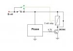
I was thinking that a way to accomplish this is to have a darlington transistor connected to the picaxe in parallel to the switch. And the gate of the transistor is controlled by the picaxe. That way, when the power is turned on, the 5v is going through the switch and to the picaxe, and then the picaxe turns on and sends 5v to the gate of the transistor. Then if the power is switched off, power will still be sent to the picaxe because the gate is still receiving 5v from the picaxe.
Then the picaxe will know to continue to send 5v to that gate until the hook is lowered and then stop the 5v to that gate, shutting off the power supply to itself.

This seems to make sense in my head, but it is not working at all.


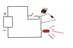
I have made a simple circuit to try to figure out what is wrong, but even that isnt working and it doesnt make sense to me.
here is a diagram of the circuit: http://imgur.com/DrNCK0c
I would assume that when you turn the switch on, the led turns on and 5v goes from pin 3 back to pin 1 (gate) of the transistor so that when the switch turns back off, the transistor is still activated and the led stays on.
The transistor is a tip102.

I feel like I'm going to feel pretty stupid when the simple answer is given. haha


Thanks for any help
 

eclectic

Moderator
I'll leave the switching answer to those more expert.
However, a couple of requests.

1. Please attach images,
to save others going to unknown sites,
or not bothering at all.

2. Even if you use Paint or whatever,
try and use the "accepted" symbols.

Learning them, or knowing where to find them,
is extremely useful.

e
 

Attachments

I'll leave the switching answer to those more expert.
However, a couple of requests.

1. Please attach images,
to save others going to unknown sites,
or not bothering at all.

2. Even if you use Paint or whatever,
try and use the "accepted" symbols.

Learning them, or knowing where to find them,
is extremely useful.

e
yep I was going to use all correct symbols, but then I thought that people might ask for a picture of the setup incase I had actually wired the pins differently than what I had shown in the circuit.
With pictures of the components you can see where I actually wired the pins.

But I will know that for next time. Thanks
 

eclectic

Moderator
yep I was going to use all correct symbols, but then I thought that people might ask for a picture of the setup incase I had actually wired the pins differently than what I had shown in the circuit.
With pictures of the components you can see where I actually wired the pins.

But I will know that for next time. Thanks
A "picture" means at least two high-resolution

photographs,

taken from 90° above and below the

real

circuit board.

e
 

hippy

Ex-Staff (retired)
With pictures of the components you can see where I actually wired the pins.
Unfortunately that's not a picture of what you have but a diagram showing what you think you have so it's not really any more useful than a circuit or picture.

I guess you are trying to create a high side switch which remains powered once it has been turned on. Starts up when +V applied to its base via the switch and then keeps the base high from the emitter via the diode. Unfortunately I'm no exert in such things but it might help others come up with an answer.
 

Paix

Senior Member
So, what is the Transistor. The package is relevant for voltage regulators, temperature sensors, FET and Bipolar transistor types.

Diode and Transistor type would actually help and allow others to know if your connection is as it should be. All transistors with the same package outline don't have the same connections for their elements.
I said in the post it's a tip102
 

Hemi345

Senior Member
How far along are you with your project?

Could you add an NPN to control the TIP102, do away with the power switch and just use the button for power and raise the hook?

See schematic below.

Pressing the button would power up the PICAXE. Code would put C.4 high to keep the PICAXE powered even when the button was released. Pressing the button would show high on C.3 and raise the hook. When button is released, C.3 goes low and PICAXE lowers hook then powers itself off by putting C.4 low.

EDIT - opps, somewhere I thought I read the TIP102 was an PNP transistor. So disregard what I said above about controlling the TIP102 above. Just look at the schematic and see if that makes sense.
 

Attachments

Paix

Senior Member
Ok, sorry, I missed that.
Here is the TIP102 data sheet, showing the TO220 package and the base (!), collector(2) and emiter(3) connections with pins pointing down and flat surface down. It's a Darlington device so no Gate!

I'm not Darlington Au Fait, but what is that in the spec that says "Sustaining Voltage" 100V and is it of any consequence in the circuit under discussion?

= = = SUPERSEDED BY HEMI345 POST = = =
 
Last edited:
How far along are you with your project?

Could you add an NPN to control the TIP102, do away with the power switch and just use the button for power and raise the hook?

See schematic below.

Pressing the button would power up the PICAXE. Code would put C.4 high to keep the PICAXE powered even when the button was released. Pressing the button would show high on C.3 and raise the hook. When button is released, C.3 goes low and PICAXE lowers hook then powers itself off by putting C.4 low.

EDIT - opps, somewhere I thought I read the TIP102 was an PNP transistor. So disregard what I said above about controlling the TIP102 above. Just look at the schematic and see if that makes sense.
I think this is very close to what I need. Unfortunately I wasn't clear enough in my description of the project. my fault.
The button to turn the main power on and off cannot be the same as the button to raise and lower the hook because the button to raise and lower the hook is a touch sensitive button (which I have figured out fine)
The main power switch is just a typical flip on/off switch.

So I need the picaxe to power itself even when the flip switch is flipped off until the hook has been lowered back down.

I am trying my best to understand the circuit you sent and see if I can make the one I need out of it.
Thanks for the reply!

If you know how to fix the circuit to the way I need it that would be awesome!
 
Unfortunately I can't use any relays for this because it is for squeezing the lever of a gas pump. So I need everything to be solid state (except of course the motor and the main power switch)
 

Paix

Senior Member
Unfortunately I can't use any relays for this because it is for squeezing the lever of a gas pump. So I need everything to be solid state (except of course the motor and the main power switch)
Very good . . . from your first description, perhaps the answer is to put the power switch out of reach so that it can't be switched off whilst the lever is being squeezed.

On another note, it is fairly normal for some of the wiser forum members to advise against modifications to motor vehicles on the basis that it might invalidate their insurance etc. How wonderful to realise that you are talking about what we in the UK would refer to loosely as a forecourt petrol pump.
The hook seems to be operating the device that the nozzle rests upon and which switches off the power. Here we seem to rely upon sense for people to release the lever before returning it to rest in the pump console.

I'm sure that there should be a health warning or a cartoon here somewhere. I guess that Burlington is in the USA. The last thing you seem to need with this project is, a bright spark or two? I do see your dilemma though.

I don't suppose that an SCR might provide the sort of DC latching mechanism that you seek.
As I understand it, press the momentary contact button, take the nozzle, squeeze the trigger to deliver, release the trigger and power down the pump? The trigger squeeze being the bit that you wish to automate. I'm certainly intrigued. Is this a broken pump that you are trying to put back into service or are you just brainstorming?
 

rossko57

Senior Member
Unfortunately I can't use any relays for this because it is for squeezing the lever of a gas pump. So I need everything to be solid state (except of course the motor and the main power switch)
Is the switch mounted remotely, or a special flameproof type? It may be wise to look at putting the whole shebang in a flameproof box ... which would allow the use of relays

Anyway, consider powering the Picaxe solely through the TIP. The "power" switch can then serve only a signalling function. Feed through a diode (and resistor) so that the switch operates the TIP. Take another feed from the switch to a Picaxe input, so that it can read the state of the switch. And of course a Picaxe output (and resistor) to hold the TIP on. The diode between switch+input line and TIP+output line prevents unwanted feedback.
It's not intrinsically safe, a program error or fault in the Picaxe, its supply, or driver circuitry will not necessarily shutoff the gas. What happens if the motor opening the gas goes pop?
And presumably there is a power supply always active, necessitating some other "master" shutoff.

Is there a way to design a sprung mechanism, that will return to safe/off in the event of say a power supply fault?
 
Very good . . . from your first description, perhaps the answer is to put the power switch out of reach so that it can't be switched off whilst the lever is being squeezed.

On another note, it is fairly normal for some of the wiser forum members to advise against modifications to motor vehicles on the basis that it might invalidate their insurance etc. How wonderful to realise that you are talking about what we in the UK would refer to loosely as a forecourt petrol pump.
The hook seems to be operating the device that the nozzle rests upon and which switches off the power. Here we seem to rely upon sense for people to release the lever before returning it to rest in the pump console.

I'm sure that there should be a health warning or a cartoon here somewhere. I guess that Burlington is in the USA. The last thing you seem to need with this project is, a bright spark or two? I do see your dilemma though.

I don't suppose that an SCR might provide the sort of DC latching mechanism that you seek.
As I understand it, press the momentary contact button, take the nozzle, squeeze the trigger to deliver, release the trigger and power down the pump? The trigger squeeze being the bit that you wish to automate. I'm certainly intrigued. Is this a broken pump that you are trying to put back into service or are you just brainstorming?
It is for a school project. A woman with arthritus has trouble squeezing the lever and we need to design a device that simplifies this task for her.
So whilst others are busy making levers and such, I figured why not make something that eliminates her need to use any of her own strength. Simply power this device with your car battery as you would any gps or cell phone and all you have to do is press the touch sensative button to have the hook squeeze the lever.

However one constraint with the project is that a device that props the lever closed is illegal here in Canada. This is because people will prop it closed, go back and sit in their car (generating static) then once the gas is done pumping, grab the nozzle and create a spark and fire.

So with this design, though it does hold the nozzle open, the user must be present at all times pressing the touch sensative button. As soon as they let go, or turn the main power off, the hook releases.


I just tested the circuit with a small relay I had. It works great with the relay. I think that this should be fine because the current going through the picaxe is very small so any sparks created by the relay would be negligible.

So I no longer need assistance in that respect.

But if this is still a topic worth discussing for others, feel free!
 
I thought about that, but unfortunately not with the design I have right now. I am using a small dc motor with a gear box on the end with a gear ratio of 396:1. This way it has very high torque and low speed and when the hook reaches the top, the motor doesnt need any power to keep it there because the gear ratio is so high it essentially locks in place. Great for saving power (because you dont need continuous power to hold it there) but yes very flawed if say the battery ran out when the hook was at the top.

This project is already a million times overkill on what it needs to be, so I'm not to worried about it.
 

Hemi345

Senior Member
With just a slight change, this can be used with the switch. Same thing as before. Flipping switch on, powers PICAXE. PICAXE puts C.4 high. The program only puts C.4 low if the motor is in down position. sghioto is right, i forgot the CLR on the PNP base in my earlier schematic. I also added a CLR on C.3 just to be safe.
 

Attachments

Paix

Senior Member
Sorry if I was being a bit hard on you, but it did at least get a lot more context about your project from you and therefore help others who are more able to give you advice better suited to your issues.

Sealed relay?
 
yep its sealed so I'm sure it's not an issue! And no you weren't hard on me! thats the same questions I will be asked when presenting it anyways!
 

premelec

Senior Member
I'm not clear on how you are getting a geared motor to release - or are you going to reverse it? In the application you describe I'd think immediate release is necessary and a highly geared motor usually wouldn't go fast with spring tension for instance. I installed a cruise control in an old VW which had a motor and lead screw to pull a cable and a solenoid to pop the lead nut off the lead screw if you stepped on the brakes. I also think your motor better be brushless as commutators spark a lot... good luck with the project.
 

rossko57

Senior Member
Thought on the mechanism; add a solenoid to engage the pulling-hook with the gas handle, with a spring to pull it off. Then the motor/gearbox can do the pulling. This would allow immediate disengagement (the pull motor can wind itself back later, or at next use) and to satisfy safety will pop off in the event of power failure, operator falling over, etc.

'Solenoid' can take the form of a geared motor, so long as it doesn't mind being stalled and it can freewheel back under spring pressure i.e. no worm drive.

Getting such mechanisms working reliably is not easy mind, especially if you have to cater for various gas pump designs.

There are sound reasons why the standard gas pump shouldn't be propped open, I would expect students on this project would need to understand those reasons so as to take account of them in their design, and write it all up :)

Have you taken account of the gas pump's self-disengaging feature? Maybe yours are different (doubt it) but when filling a tank to the brim the squeeze lever can kick out really hard as the end of the nozzle is covered. It's potentially damaging to the project (what if it jams it open) and more importantly it's a safety feature ... really the project needs to "see" that kick and immediately disengage itself. That could be a mechanism too - a kind of 'breakable' hook in the project.

Actually thinking on that a bit more ... most levers don't kick out (here) any more, they sort of break internally instead. No problem.
 
Top