Schematic question

buntay

Senior Member
Greetings fellow picaxers,

I request a little help on electrics.
What and why:

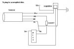
I need to count rpm’s and I am planning on using an LED with photocell or IR emitter and detector.
I have a disk with 2 holes that I will shine through one side and catch on the other. I am planning on using the count method for my capture method. With that being said here are my questions.

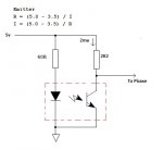
Looking at the sheets on what I am planning on using my IR emitter says forward voltage 1.5 , 1.8v max@ 50mA with a reverse voltage of 5v. My question is what is the schematic for powering it with 5v and does it stay on like a led or do I need to pulse it.

For the LED version the led says 3.5v max. What is the schematic for 5v.
Electronic design Is NOT my strong point and any help is greatly appreciated.
 

Dippy

Moderator
An IR emitter like that IS an LED which radiates predominatly IR light.
Simplest solution = Resistor to limit the current ... just like you would with a 'normal' LED.
i.e. Ohm's Law with allowance for Forward voltage drop across IRLED.
R = (Vsupply - Vforward) / Irequired.
 

westaust55

Moderator
If your project, or at least the disk part is enclosed to a segregated from other light sources then a permanently active LED (visible or IR) will suffice.
If in bright light or outdoors then a pulsed output using. 38khz on the IR LED and and IR receiver designed for 38kHz will likely be better as the modulation is at a frequency where sunlight has least impact.
 

Goeytex

Senior Member
You do not need to pulse the LED. The Pulse is generated when the wheel makes & breaks the light beam.

The diagram below should be close to what you need.
 

Attachments

Dippy

Moderator
I would say that you should avoid modulation if possible/practical.
It really depends on environment and how big your RPMs are.

The modulated receiver chips take a finite time to decode an on-off so fast RPMs may result in no-signal.
I haven't done any calcs but it is something to consider, though also consider that the faster the modulation then (in theory) the faster the decoding time and therefore the faster the RPM you can detect. Depends on your app and whether any workarounds can be devised.
 

Dippy

Moderator
"It didnt give me the values I received here."
- show us your calculations. It looked fine to me.
How did you calculate?
 

Dippy

Moderator
5-3.5 = 1.5V

Divide the 1.5 by 0.05 (50mA)
= 30 Ohms. Same as on-line calc you linked to. It's really a very simple calc.

Ummm... How did you do it?
List your method of calculation (like I did above).
Or did you just stuff numbers into the calculator page? :)
 

buntay

Senior Member
just stuffed numbers into the calculator. But was able to figure out the voltage drop from your formula. Wasnt able to do the math as I am not very good with terms like
R = (Vsupply - Vforward) / Irequired.
they are all greek to me,maybe a laymen's explanation would have helped,:) but figured them out enough to get the job done. While working on that a co-worker found the web page. But didnt come up with the same numbers goeytex's photo so got a little confused as to what #'s I should use.:eek:

Thanks for the help, my electronics expertise comes from a 200 in one science lab kit I got when i was 10.........and researching internet but again the technical terms and formulas have me at a loss. maybe should see if there is a layman's book of electronics exists.....hahaha
 

eclectic

Moderator
just stuffed numbers into the calculator. But was able to figure out the voltage drop from your formula. Wasnt able to do the math as I am not very good with terms like they are all greek to me,maybe a laymen's explanation would have helped,:) but figured them out enough to get the job done. While working on that a co-worker found the web page. But didnt come up with the same numbers goeytex's photo so got a little confused as to what #'s I should use.:eek:

Thanks for the help, my electronics expertise comes from a 200 in one science lab kit I got when i was 10.........and researching internet but again the technical terms and formulas have me at a loss. maybe should see if there is a layman's book of electronics exists.....hahaha
There is a "layman's guide"
(well actually it's for intelligent teenagers)
http://www.kpsec.freeuk.com/

It's been mentioned many times on the Forum

And, Goeytex's example used a "safe" value of 25mA

50mA is absolute max and can shorten the life of the LED

e
 

buntay

Senior Member
And, Goeytex's example used a "safe" value of 25mA

50mA is absolute max and can shorten the life of the LED
Thank you sir, thats a good thing to know.....yet another lesson learned:)
 

buntay

Senior Member
ok lets see if I am getting a handle on this resistance to achive safe levels from raw voltage.

if I am feeding a proximity sensor with 12v and need a picaxe safe 4v @10 mA I need a 470 Ohm 1/4 watt resistor on the "+" line between the sensor and picaxe useing a common ground?
is this correct?
 

westaust55

Moderator
Sorry, but your description is too vague to confirm.

How about posting a schematic of what you envisage.

The earlier provided formula:
R = (Vsupply - Vforward) / Irequired.
related to LEDs and calculating the required series resistors.

We need specific information about the new item – the proximity sensor.
How is it connected – seems from your comment it operates from 12V.
If you have a digital pulse train which you want to feed into the PICAXE then two resistors as a potential divider to drop from 12V to the PICAXE supply voltage level is likely the simplest option.

Is the proposed circuit akin to the attached?
 

Attachments

Last edited:

buntay

Senior Member
hope this helps.

do you have any idea what its like to be able to program but not put the electronics with it.:eek:schm.JPG
 

Goeytex

Senior Member
If I may ....

The value of R2 is somewhat arbitrary. We know we have a 12 volt signal and that we are constructing voltage divider. The Picaxe needs very little current and we don't want to waste power using low R values. So with 12v and at least a 4K7 resistor the most current than can flow through the divider to ground is 12 / 4700 or about 2.5 ma. It will be less because the seconds resistor has not yet been calculated.

Another way to do it is to select the total current through the divider and then figure for the resistor values. Let's say we want the current to be 1 ma. 12v / .001 = 12,000 ohms total. Now we select resistor values for the divider so that the voltage drop across R2 = V Picaxe. If we need 5v and have 1ma then the resistor value will be 5k. So we subtract 5K from 12K and get 7K for the other resistor.

But 7K is a non standard value so we use 4.7K and 6.8K instead and get close enough.

You could also use values of 3k3 and 4K7 to get the same result only the current will be 1.5 ma instead of 1 ma

After you have been doing this for a while you will see why resistor values of 6K8, 4K7, 3k3 & 2K2 are used so much.
 
Last edited:

caver451

New Member
hope this helps.

do you have any idea what its like to be able to program but not put the electronics with it.:eek:View attachment 9977
I suspect you're getting good answers in this thread, but not necessarily the answers you are looking for. For most technical problems, there is "more than one way to do it," and I suspect everyone is giving you answers based on what they're guessing or assuming you're trying to do.

Do you have the part number and manufacturer of this proximity sensor you are considering? I think if we can look at that, you're going to have a much better chance of getting appropriate advice. If your sensor is sending a 12v logic pulse, I suspect your sensor isn't appropriate for this application... Perhaps if we knew exactly what you're trying to measure the RPM of we could help pick a better sensor?

On a slightly different note, I strongly recommend you look up and study Ohm's Law. Don't just memorize the formulas, but work towards understanding why the formulas are the way they are and how voltage, current and resistance are related. Literally everything in electronics is based on Ohm's Law. It's the very foundation for everything you're going to be doing. Once you understand it, you will not only know what resistor values to pick, but when you will need a resistor in the first place!

Please take this advice in the spirit it is being offered! I remember being quite frustrated and confused about electronics until I realized that Ohm's Law isn't just a few formulas, but rather a description of the basic laws of electronics. If you memorize the formulas, you can calculate the values. If you understand the laws, however, you'll know when you need those resistors and why!

One last thing... if your voltage regulator is an LM7805, the middle pin is ground. Hold it so you can read the writing. Pin 1 is on the left, pin 2 is the middle, pin 3 is on the right. Pin 1 is the input, pin 2 is ground, pin 3 is the output. Usually you'll want a 0.33mfd capacitor tying pin 1 to pin 2, and a 0.1mfd capacitor typing pin 3 to pin 2. That will help take some noise out of the output, though if you're running this from a battery, it probably doesn't matter...
 
Top