The problem
A lot, if not most, PICAXE applications use a super loop architecture.
but this approach will only work if you know the precise duration of each task and these durations never vary. If any of the task durations are variable then it is almost impossible to achieve precisely scheduled tasks with this approach.
A solution
This is where a sandwich delay comes to the rescue.
Between 1999 and about 2014 there was research being done on the development of highly reliable embedded systems using a time-triggered architecture. This seems to have been done mainly at the Univesity of Leicester and the research is described as being targetted at "low-cost, resource-constrained microcontrolles" where the hardware might include "an 8-bit or 16/32-bit microcontroller with very limited memory and CPU performance" and the code was intended to be used in compiled C programs on these small microcontrollers.
The descriptions of "Resource-constained" and "an 8-bit microcontroller with very limited memory and CPU performance" certianly applies to the PICAXE chips so the sandwich delay caught my attention as something that was worth testing to to see if it could be used to improve the scheduling of timed tasks running in super loops on the PICAXE chips.
This post is my implementation, for the PIXAXE X2 chips, of the following sandwich delay example:
The implementation of a sandwich delay
The sandwich delay uses a hardware timer.
i.e. the start of the sandwich delay always involves starting a hardware timer with this code:
The wait for the sandwich delay is implemented by putting the chip into a low power state using the DOZE command . At the completion of this sandwich delay wite the hardware timer interrupt wakes the chip from the DOZE and the PICAXE firmware simply continues on with the next BASIC command. i.e. no PICAXE BASIC commands need to be executed as a part of waiting for the sandwich delay to complete.
NOTES:
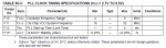
This approach uses the SETTIMER and DOZE commands so it can only be used on the X2 chips.
For the SETTIMER command the manual states "Timer cannot be used at the same time as the servo command, as the servo command requires sole use of the timer to calculate the servo pulse intervals."
For the DOZE command the manual states "all timers are left on and so the pwmout, timer and servo commands will continue to function". The use of SETTIMER already means that the timer and servo commands will not operate correctly. You might be able to use the pwmout command as it sounds like it does not use the SETTIMER timer.
The DOZE command means that the chip will use less power when tasks are not actually executiing making this approach also useful for battery powered applications.
Disclaimer: This approach relies on the hardware interrupt that occurs when the hardware timer overflows to 0. This behaviour is an undocumented feature of the PICAXE firmware so you use it at your own risk. I've tested it on a 20X2 chip so I expect it should work on the other X2 chips but they are untested.
My investigation with Hippy into the hardware timer interrupt is in this post Setting an interrupt on the timer 0 overflow appears to cause a hardware interrupt at 8x the timer interrupt frequency where we confirmed that the hardware interrupt occurs at 8 x the frequency of the SETTIMER preload value you set for the PICAXE polled timer interrupt. i.e. if you SETTIMER t1s_8 at 8MHz so that the TIMER value will increment every 1 sec then the hardware timer interrupt will occur every 125ms. This means that you will need to allow for this factor of 8 when you calculate the timer preload value to use for your task sandwich delays.
and the timer 1 hardware interrupt behaviour I am using is described in this post by Hippy The hardware timers - utilisation - Post #10
"There is no need to define a polled interrupt using SETINTFLAGS and you do not need to create an INTERRUPT subroutine."
Not needing to create an INTERRUPT subroutine is an advantage as it reduces the overhead of the interpreted PICAXE BASIC commands that need to be executed when using this technique.
Finally, the advice about when to use this type of task scheduling is "to use the simplest super loop that works".
E.g. flashing a LED at 1s probably does not need a sandwich delay and the simpler approach of using fixed PAUSE or PAUSEUS commands would likely be a better solution.
Performance
My gauge for how well the sandwich delay works is how precise the sandwich delay is and how it compares to the precision of a simple task that has just one TOGGLE command and one PAUSEUS command. If the sandwich delay time varies by a lot or if the variation in the sandwich delays is much more than the then variation of a simple PAUSEUS task then the sandwich delay does not perform well.
The tasks in the implementation code above have a TOGGLE B.0 as the first command for both tasks 1 and 2.
And this is code for the two tasks I used to measure the jitter of simple PAUSEUS 10000 and 5000 tasks:
I paste the measured duration of 2000 high pulses using the PULSIN command on a 2nd 14M2 chip running at 16MHz into a spreadsheet to calculate the jitter.
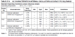
These are the results:
Measured Jitter
Task 1 TOGGLE B.0; PAUSEUS 10000 -0.55% to +0.56%
Task 2 TOGGLE B.0; PAUSEUS 5000 -0.58% to +0.52%
Task 1 50ms sandwich delay -0.46% to +0.45%
Task 2 100ms sandwich delay -0.47% to +0.49%
So the jitter is about the same for different lengths of the sandwich delay and about the same as the jitter for simple PAUSEUS 10000 and PAUSEUS 5000 tasks.
NOTE: Using PULSIN on the 14M2 at 16MHz means that the measured duration of the high pulses has a resolution of 2.5us. This probably effects the accuracy of these measurements so I don't think that we should reading too much into the slightly lower jitter for the sandwich delay tests.
A lot, if not most, PICAXE applications use a super loop architecture.
- It has the advantages that it is simple, and therefore easy to understand, and that it consumes virtually no system memory or CPU resources.
- It has the limitation that it is very difficult to execute a task at precise intervals of time.
Code:
main:
    <code for task 1>
    pauseus XX
    <code for task 2>
    pauseus YY
goto main:A solution
This is where a sandwich delay comes to the rescue.
Between 1999 and about 2014 there was research being done on the development of highly reliable embedded systems using a time-triggered architecture. This seems to have been done mainly at the Univesity of Leicester and the research is described as being targetted at "low-cost, resource-constrained microcontrolles" where the hardware might include "an 8-bit or 16/32-bit microcontroller with very limited memory and CPU performance" and the code was intended to be used in compiled C programs on these small microcontrollers.
The descriptions of "Resource-constained" and "an 8-bit microcontroller with very limited memory and CPU performance" certianly applies to the PICAXE chips so the sandwich delay caught my attention as something that was worth testing to to see if it could be used to improve the scheduling of timed tasks running in super loops on the PICAXE chips.
This post is my implementation, for the PIXAXE X2 chips, of the following sandwich delay example:
Code:
while(1)
{
    Start_Sandwich_Delay(A); // Set timer to match fn. duration
    FunctionA();
    Wait_For_Sandwich_Delay_To_Complete();

    Start_Sandwich_Delay(B);
    FunctionB();
    Wait_For_Sandwich_Delay_To_Complete();

    Start_Sandwich_Delay(C);
    FunctionC();
    Wait_For_Sandwich_Delay_To_Complete();
}
The sandwich delay uses a hardware timer.
i.e. the start of the sandwich delay always involves starting a hardware timer with this code:
Code:
SETTIMER OFF
SETTIMER <preload value for this sandwich delay duration>
Code:
#PICAXE 20X2

#NO_DATA
#NO_TABLE

SETFREQ M8

; A timer tick occurs every 4us @8MHz
#DEFINE TIMER_8MHz_10mS        63036
#DEFINE TIMER_8MHz_20mS        60536
#DEFINE TIMER_8MHz_30mS        58036
#DEFINE TIMER_8MHz_50mS        53036
#DEFINE TIMER_8MHz_100mS        40536
#DEFINE TIMER_8MHz_200mS        15536
#DEFINE TIMER_8MHz_250mS        3036

; VARIABLES
SYMBOL    RANDOM_SEED    = W1    ; B3:B2
SYMBOL    TEMP_W0         = W0    ; B1:B0

; INITIALIZATION
HIGH B.0                    ; Initialize B.0 low measure the task 1 sandwich delay duration and high to measure task 2 sandwich delay duration
READADC C.1, RANDOM_SEED        ; Initialize the seed for the RANDOM() function

main:
    SETTIMER OFF
    SETTIMER TIMER_8MHz_50mS    ; Set the sandwich delay for this task
    TOGGLE B.0                ; Toggle B.0 at the start of the task 1 slot
    GOSUB task_1
    DOZE 0                ; Put the chip to sleep until the next hardware timer interrupt

    SETTIMER OFF
    SETTIMER TIMER_8MHz_100mS    ; Set the sandwich delay for this task
    TOGGLE B.0                ; Toggle B.0 at the start of the task 1 slot
    GOSUB task_2
    DOZE 0                ; Put the chip to sleep until the next hardware timer interrupt
goto main

task_1:                    ; Task 1 is a random delay in the range 0 - 39.9 ms
    RANDOM RANDOM_SEED
    TEMP_W0 = RANDOM_SEED // 4000
    pauseus TEMP_W0
return

task_2:                    ; Task 2 is a random delay in the range 0 - 89.9 ms
    RANDOM RANDOM_SEED
    TEMP_W0 = RANDOM_SEED // 9000
    pauseus TEMP_W0
returnThis approach uses the SETTIMER and DOZE commands so it can only be used on the X2 chips.
For the SETTIMER command the manual states "Timer cannot be used at the same time as the servo command, as the servo command requires sole use of the timer to calculate the servo pulse intervals."
For the DOZE command the manual states "all timers are left on and so the pwmout, timer and servo commands will continue to function". The use of SETTIMER already means that the timer and servo commands will not operate correctly. You might be able to use the pwmout command as it sounds like it does not use the SETTIMER timer.
The DOZE command means that the chip will use less power when tasks are not actually executiing making this approach also useful for battery powered applications.
Disclaimer: This approach relies on the hardware interrupt that occurs when the hardware timer overflows to 0. This behaviour is an undocumented feature of the PICAXE firmware so you use it at your own risk. I've tested it on a 20X2 chip so I expect it should work on the other X2 chips but they are untested.
My investigation with Hippy into the hardware timer interrupt is in this post Setting an interrupt on the timer 0 overflow appears to cause a hardware interrupt at 8x the timer interrupt frequency where we confirmed that the hardware interrupt occurs at 8 x the frequency of the SETTIMER preload value you set for the PICAXE polled timer interrupt. i.e. if you SETTIMER t1s_8 at 8MHz so that the TIMER value will increment every 1 sec then the hardware timer interrupt will occur every 125ms. This means that you will need to allow for this factor of 8 when you calculate the timer preload value to use for your task sandwich delays.
and the timer 1 hardware interrupt behaviour I am using is described in this post by Hippy The hardware timers - utilisation - Post #10
"There is no need to define a polled interrupt using SETINTFLAGS and you do not need to create an INTERRUPT subroutine."
Not needing to create an INTERRUPT subroutine is an advantage as it reduces the overhead of the interpreted PICAXE BASIC commands that need to be executed when using this technique.
Finally, the advice about when to use this type of task scheduling is "to use the simplest super loop that works".
E.g. flashing a LED at 1s probably does not need a sandwich delay and the simpler approach of using fixed PAUSE or PAUSEUS commands would likely be a better solution.
Performance
My gauge for how well the sandwich delay works is how precise the sandwich delay is and how it compares to the precision of a simple task that has just one TOGGLE command and one PAUSEUS command. If the sandwich delay time varies by a lot or if the variation in the sandwich delays is much more than the then variation of a simple PAUSEUS task then the sandwich delay does not perform well.
The tasks in the implementation code above have a TOGGLE B.0 as the first command for both tasks 1 and 2.
- If I initialize B.0 LOW then the high pusle is the duration of the sandwich delay for task 1
- If I initialize B.0 HIGH then the high pusle is the duration of the sandwich delay for task 2
And this is code for the two tasks I used to measure the jitter of simple PAUSEUS 10000 and 5000 tasks:
Code:
; INITIALIZATION
LOW B.0
SETFREQ M8

main:
    ; Task 1
    toggle B.0
    pauseus 10000

    ; Task 2
    toggle B.0
    pauseus 5000
goto mainThese are the results:
Measured Jitter
Task 1 TOGGLE B.0; PAUSEUS 10000 -0.55% to +0.56%
Task 2 TOGGLE B.0; PAUSEUS 5000 -0.58% to +0.52%
Task 1 50ms sandwich delay -0.46% to +0.45%
Task 2 100ms sandwich delay -0.47% to +0.49%
So the jitter is about the same for different lengths of the sandwich delay and about the same as the jitter for simple PAUSEUS 10000 and PAUSEUS 5000 tasks.
NOTE: Using PULSIN on the 14M2 at 16MHz means that the measured duration of the high pulses has a resolution of 2.5us. This probably effects the accuracy of these measurements so I don't think that we should reading too much into the slightly lower jitter for the sandwich delay tests.
Last edited: