RTC Module from eBay - early recommendation

PaulRB

Senior Member
All,

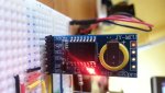
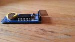
Recently took delivery of two DS3231 based I2C Real Time Clock (RTC) modules from China purchased on eBay for about £4 each including p&p:

http://www.ebay.co.uk/itm/RTCpro-DS3231-Precision-Clock-Module-With-Temperature-Arduino-For-AVR-PIC-51-ARM-/150978644976?pt=LH_DefaultDomain_0&hash=item2327074bf0

They took about 30 days to arrive, but the tracking number given showed that the seller dispatched the item only 2 days after I placed the order, so not their fault.

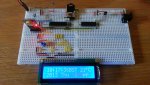
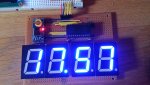
So far so good, had them working in 1/2 hr. Supposed to be more accurate than the more common DS1307 types, drifting only by a minute or so per year. Time will tell... Also has built in temperature sensor good enough for simple applications. Seems reasonably accurate when compared to other temp sensors around my house - weather station etc.

20130418_101855.jpg20130418_101738.jpg

Paul
 

g6ejd

Senior Member
Neat, I'm getting one of these now, that's a really good price too. I like the bread-board approach and I might do that with my Arduino bare-bones kit rather than put it on vero/strip-board. Thanks for sharing the pics.
 

MartinM57

Moderator
Almost worth buying to stick in a frying pan and getting the DS3231 off for use elsewhere - if one could guarantee it wasn't counterfeit.

I have some of the DS1307 cheapy look-a-likey boards with 3.6v rechargeable CR2032 cells - I have severe doubts that the DS1307 on those come from a reputable fab house

But if they work for you, and you don't mind potentially funding some dodgy Chinese oufit, a nice find.
 

westaust55

Moderator
Futurlec sell a similar RTC module using the Ds3232 for about $15 but the freetronics module is a whopping $29.
Both modules come with back-up battery and a potential advantage of these Ds3232 is the inclusion of 236 bytes of battery backed RAM.

Certainly the accuracy of the DS3231/3232 chips is better than the DS1307.
I started writing an article a couple of months ago but became side tracked. Should try and wrap up the weekend.
 
Last edited:

Pongo

Senior Member
There are DS3234 (same accuracy spec as the DS3232/better than the DS3231) modules on ebay for about $10.
 

PaulRB

Senior Member
A cautionary tale:

Finally got around to permanently soldering one of my RTC modules to stripboard. I wanted to fix the RTC flat to the stripboard, so this meant that the right-angle headers had to be removed in favour of straight ones. Easy Peasy, I thought... No.

When I finally got it done, I was close to 100% certain I had ruined the RTC module's connections and it would no longer work. Getting the right-angle headers off was like pulling my own teeth (I imagine). I was delighted but absolutely incredulous when I connected the circuit back up and it worked!

Can the forum members recommend a procedure for removing such things?

If I had to do it again (and I will avoid the experience if at all possible), I would cut the right-angle connectors off just above the black plastic insulators. Then slide the insulators off with pliers. Next I would use solder pump and solder wick to remove as much solder as I could on BOTH sides of the board. Finally, I would carefully work the remains of each pin out with pliers from the top side, applying the soldering iron from the bottom side. Unless you have three hands, you will need a clamp/vice of some sort to hold the board, but be careful not to damage it in the vice. "Helping hands" won't help, as too much force seemed to be needed to remove the pins. Maybe the holes in the board are slightly too narrow.

20130527_180055.jpg20130527_175706.jpg

Paul
 

hippy

Ex-Staff (retired)
I wanted to fix the RTC flat to the stripboard, so this meant that the right-angle headers had to be removed in favour of straight ones. Easy Peasy, I thought... No.
I've discovered the same on many boards and I'd agree with removing the plastic and unsoldering the legs one at a time but it can still require quite some effort to work a leg free from a plated-through hole, and often not without causing damage or lifting PCB tracking off as well. There are alternatives -

You can often straighten the legs out using a set of pliers or a vice without causing damage to a board. That may mean mounting top-side down but that may not necessarily be a problem.

It should be possible to trim the pins and solder new connectors onto the remains, or on to the back of the board, then trim the front pins down.

It may even be possible to bend the legs back round on themselves and add another set of pins as an extension.
 

g6ejd

Senior Member
If I had to do it again (and I will avoid the experience if at all possible), I would cut the right-angle connectors off just above the black plastic insulators. Then slide the insulators off with pliers. Next I would use solder pump and solder wick to remove as much solder as I could on BOTH sides of the board. Finally, I would carefully work the remains of each pin out with pliers from the top side, applying the soldering iron from the bottom side. Unless you have three hands, you will need a clamp/vice of some sort to hold the board, but be careful not to damage it in the vice. "Helping hands" won't help, as too much force seemed to be needed to remove the pins. Maybe the holes in the board are slightly too narrow.
I've got one of these and this is exactly what I do, I learnt the hard way doing similar on an Arduino, with 2 x 20 pins, cutting the headers and pulling one by one with wick is the best way, unless you purchase the iron attachments that allow whole header heating for a single pull, if you have 5-hands :)

BTW the accuracy of these RTC is amazing, it's keeping time (4-weeks now) with my radio controlled clock, so the 1-2 PPM spec. is good.
 

bpowell

Senior Member
Can the forum members recommend a procedure for removing such things?
You're on the right track...I almost always remove pin-by-pin...this goes against my "Salvage and use later" mentality...but when it comes to header connectors, once they're in, they're IN!

Then, counter-intuitively, I will typically ADD solder to a pin...and then, once ALL of the solder (my "add" as well as the factory solder) is liquid on both sides, I just gently slide the pin out...no muss, no fuss...rinse and repeat for all the pins, THEN follow-up with wick to remove the solder and reveal clean (and tinned) through-holes ready for a new header...

That's how I do it at least.
 

Hemi345

Senior Member
I gob a bunch of fresh solder on a big iron tip and make a long solder bridge across all the pins. Once the entire length is liquid, i can usually pull the entire header out as one. Need to use a heavy vice to hold the board. Then clean up with solder wick.

I have a DS1337+ and once i got a decent 6pF crystal it has been pretty accurate... but it is also running in my basement where the temp stays between 60-70F year around. If it was any place else, i'd go with the DS3232, with temp compensation (using those on my PICAXE "mini shield base").
 
Top