      SYMBOL character1    = B2
	SYMBOL character2    = B3
	SYMBOL character3    = B4
	SYMBOL character4    = B5
	SYMBOL character5    = B6
	SYMBOL character6    = B7
	SYMBOL hours         = B8
      SYMBOL mins          = B9
	SYMBOL secs          = B10
	SYMBOL day           = B11
	SYMBOL date          = B12
	SYMBOL month         = B13
	SYMBOL year          = B14
	SYMBOL PM_AM         = B15

Program:
   HI2Csetup I2Cmaster, %11010000, I2Cslow, I2Cbyte       ' set to 100kbps
       HI2Cout $0,  ( $40, $58, $10 ,day, $02, $02 , $14) ' write time to ds3231 or ds1307  example (11.58.00 PM)
'prog time          (secs,mins,hours,day,date,month,year) ' enter hours in 24 hour format ( $0 to $23 )

Main:
pause 1000
       HI2Csetup I2Cmaster, %11010000, I2Cslow, I2Cbyte
	 HI2Cin $0,   (secs,mins,hours,day,date,month,year) ' read time

ClockDisplay:
    PM_AM ="P" : IF hours < $12 then :PM_AM = "A" : ENDIF       'indicate PM  or AM

    IF hours = $20 OR hours = $21 THEN : LET hours = hours - $6 : ENDIF
    IF hours > $12 THEN : LET hours = hours - $12 : ENDIF       '24 to 12 hour format
    IF hours = $0 THEN  : hours = $12 : ENDIF

   BcdTOASCII hours,character1,character2 : IF character1 = "0" THEN : character1 = " " : ENDIF ' zero blanking character1
   BcdTOASCII mins ,character3,character4
   BcdTOASCII secs ,character5,character6
 sertxd (CR,LF,character1,character2,".",character3,character4,".",character5,character6," ",PM_AM,"M    ") '(11.58.00 PM)

DateMonthYearDisplay:
   BcdTOASCII date ,character1,character2
   BcdTOASCII month,character3,character4
   BcdTOASCII year ,character5,character6
 sertxd (character1,character2,"/",character3,character4,"/20",character5,character6,CR,LF)' (05/11/13)

 ;http://www.picaxeforum.co.uk/showthread.php?18505-DS1307-Code-Examples


     goto main
 812.4 KB Views: 44
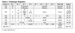
")