RGB fading with two PWMs

Jakob2803

Senior Member
I recieved some RGB LEDs recently, but my 18M2 only has 2 pins capable of PWM. I wrote this code to cycle through the colors. Is there a better way? :)
Code:
let dirsB =%11111111

main:
let pinsB =%00100010


pwmout B.6,150,0
pwmout B.3,150,255
'red out green in
for b0 = 255 to 0 STEP -1
let b1 = 255 - b0
pwmduty B.6,b1
pwmduty B.3,b0
next b0


let pinsB =%00100100

'green out blue in
pwmout B.3,150,0
for b0 = 255 to 0 STEP -1
let b1 = 255 - b0
pwmduty B.6,b0
pwmduty B.3,b1
next b0

'blue out, red in'
let pinsB =%00010100

pwmout B.3,150,0
pwmout B.6,150,0
for b0 = 255 to 0 STEP -1
let b1 = 255 - b0
pwmduty B.3,b0
pwmduty B.6,b1
next b0
goto main
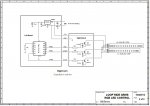
The circuit consists of the Picaxe, four transistors and the LED plus a resistor.
P1110138 (Small).JPG

This picture shows the transistor configuration (the 1s are the position of the pin in the pinsB)
P1110141 (Small).JPG
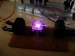
Here is a video of the result:
 

Jakob2803

Senior Member
I'm in the process of putting notes in the code so it is easier to understand.

Okay this should be better. :) I only explained the first paragraph because the rest is pretty much the same:
Code:
let dirsB =%11111111 'set all pins as outputs

main:
let pinsB =%00100010 'turn on transistors 2 (red) and 4 (green)


pwmout B.6,150,0 'start pwm, at 0 duty (otherwise there would be
'a quick flash before pwm adjustment)
pwmout B.3,150,255 'start pwm at full duty (full brightness)

'red out green in
for b0 = 255 to 0 STEP -1 'make a "for" with count down instead of up
let b1 = 255 - b0 'make b1 the "opposite" of b0, it counts up instead, from 0-255
pwmduty B.6,b1 'adjust brigthness of the green color.
pwmduty B.3,b0'adjusts the PWM brightness of B.3 (red in this case)
'to be the same as the number of times this has looped
next b0 'continue the loop


let pinsB =%00100100 'open up transistors 1 and 4 (blue and green)

'green out blue in
pwmout B.3,150,0
for b0 = 255 to 0 STEP -1
let b1 = 255 - b0
pwmduty B.6,b0
pwmduty B.3,b1
next b0

'blue out, red in'
let pinsB =%00010100 'transistors 1 and 3 (blue and red)

pwmout B.3,150,0
pwmout B.6,150,0
for b0 = 255 to 0 STEP -1
let b1 = 255 - b0
pwmduty B.3,b0
pwmduty B.6,b1
next b0
goto main
 

premelec

Senior Member
Hi - It looks like you've done well with the project! I'll mention that the 14M2 and 20M2 have 4 PWMOUTs which I've found work quite well as the PWMOUT is set and forget instead of needing refreshing like the PWM command - I just fool around with the various loops till it all looks good to me :) - and sometimes change the clock frequency to change the dimming change rate... have fun...
 

Jakob2803

Senior Member
Nice demo. I have a RGB LED that is waiting patiently for a project...

Thanks for sharing.
Thanks, good luck with yours ;)

Hi - It looks like you've done well with the project! I'll mention that the 14M2 and 20M2 have 4 PWMOUTs which I've found work quite well as the PWMOUT is set and forget instead of needing refreshing like the PWM command - I just fool around with the various loops till it all looks good to me :) - and sometimes change the clock frequency to change the dimming change rate... have fun...
Thanks. If I had known about that 14M2, no way would I have ordered three 18s. Oh well. :)

I built a make-shift lamp out of the filters inside a laptop LCD rolled up in a tube and that single RGB LED. It is still uploading but here is a video:
 

Bill.b

Senior Member
Hi

I build small amusment park rides for a christmas display. I have used RGB LED strips for one of the rides.
the 14m2 proved to be the best choice for this as it have 4 PWM outputs.
I found that count of 30 was LED OFF and 250 was full ON, not nesessary 100% of the PWM.

Code:
'loop RGB LED Control
'May 2012
'Picaxe 14M2
#picaxe 14m2
#No_Data

symbol Red 		= W2
symbol Green	= W3
symbol Blue 	= W4
symbol loopcount	= b0

symbol Redout	= c.0
symbol Blueout	= b.2
symbol Greenout	= b.4

dirsb=%00011111
dirsc=%00000111

main:

gosub fade
gosub flash
goto main


fade:	
	pwmout Redout,100,30
	pwmout Blueout,100,250
	pwmout Greenout,100,30
	pause 200
	for Red = 30 to 250
		  pwmduty Redout,Red
		  pause 20
	 next Red
	 pause 200
	 pwmduty Blueout,30
	 
	 pause 200
		for Green = 30 to 250  
		  pwmduty Greenout,Green
		  pause 20
	 next Green
	 Pause 200
	 pwmduty Redout,30
	 pause 200
	 for Blue = 30 to 250
		  pwmduty Blueout,Blue
		  pause 10
	 next Blue
	 pause 200
	 
	 for Blue = 250 to 30 step -1
		  pwmduty Blueout,Blue
		  pwmduty Greenout,blue
		  pause 20
	 next Blue
	
	pause 50
		for Red = 30 to 250
		  pwmduty Redout,Red
		   pwmduty Greenout,red
		  pause 10
	 next Red
	 pause 200
		
	for Blue = 30 to 250
		  pwmduty Blueout,Blue
		  pause 20
	 next Blue
	 pause 200
	 for Green = 250 to 30 step -1
		  pwmduty Greenout,Green
		  pause 20
	 next Green
	 Pause 50
	
	 pwmduty Redout,30
	 pause 200
	
	pwmout Redout,off
	pwmout Blueout,off
	pwmout Greenout,off

	return
	

flash:
	low greenout
	low redout
	low blueout
	for red = 1 to 4
		for loopcount = 1 to 6
			high Redout
			pause 2000
			low redout
			high greenout
			pause 2000
			low greenout
			high blueout
			pause 2000
			low Blueout
		next loopcount
		for loopcount = 1 to 4
			high Redout
			high greenout
			pause 2000
			low redout
			high greenout
			high blueout
			pause 2000
			low greenout
			high blueout
			high Redout
			pause 2000
			high greenout
			high blueout
			high Redout
			pause 2000
			low greenout
			low blueout
		next loopcount
			pause 2000
		low greenout
		low blueout
		
	next red
	pause 2000
	low redout
	return
Schematic:

looplits.jpg

Bill
 

Jakob2803

Senior Member
Hi

I build small amusment park rides for a christmas display. I have used RGB LED strips for one of the rides.
the 14m2 proved to be the best choice for this as it have 4 PWM outputs.
I found that count of 30 was LED OFF and 250 was full ON, not nesessary 100% of the PWM.

Code:
'loop RGB LED Control
'May 2012
'Picaxe 14M2
#picaxe 14m2
#No_Data

symbol Red 		= W2
symbol Green	= W3
symbol Blue 	= W4
symbol loopcount	= b0

symbol Redout	= c.0
symbol Blueout	= b.2
symbol Greenout	= b.4

dirsb=%00011111
dirsc=%00000111

main:

gosub fade
gosub flash
goto main


fade:	
	pwmout Redout,100,30
	pwmout Blueout,100,250
	pwmout Greenout,100,30
	pause 200
	for Red = 30 to 250
		  pwmduty Redout,Red
		  pause 20
	 next Red
	 pause 200
	 pwmduty Blueout,30
	 
	 pause 200
		for Green = 30 to 250  
		  pwmduty Greenout,Green
		  pause 20
	 next Green
	 Pause 200
	 pwmduty Redout,30
	 pause 200
	 for Blue = 30 to 250
		  pwmduty Blueout,Blue
		  pause 10
	 next Blue
	 pause 200
	 
	 for Blue = 250 to 30 step -1
		  pwmduty Blueout,Blue
		  pwmduty Greenout,blue
		  pause 20
	 next Blue
	
	pause 50
		for Red = 30 to 250
		  pwmduty Redout,Red
		   pwmduty Greenout,red
		  pause 10
	 next Red
	 pause 200
		
	for Blue = 30 to 250
		  pwmduty Blueout,Blue
		  pause 20
	 next Blue
	 pause 200
	 for Green = 250 to 30 step -1
		  pwmduty Greenout,Green
		  pause 20
	 next Green
	 Pause 50
	
	 pwmduty Redout,30
	 pause 200
	
	pwmout Redout,off
	pwmout Blueout,off
	pwmout Greenout,off

	return
	

flash:
	low greenout
	low redout
	low blueout
	for red = 1 to 4
		for loopcount = 1 to 6
			high Redout
			pause 2000
			low redout
			high greenout
			pause 2000
			low greenout
			high blueout
			pause 2000
			low Blueout
		next loopcount
		for loopcount = 1 to 4
			high Redout
			high greenout
			pause 2000
			low redout
			high greenout
			high blueout
			pause 2000
			low greenout
			high blueout
			high Redout
			pause 2000
			high greenout
			high blueout
			high Redout
			pause 2000
			low greenout
			low blueout
		next loopcount
			pause 2000
		low greenout
		low blueout
		
	next red
	pause 2000
	low redout
	return
Schematic:

View attachment 11521

Bill
Thanks you, great setup! What do those capacitors next to the transistors do? :)
 

Bill.b

Senior Member
I found that a small amount of intergation was required for smoth transition.
the LEDs would attain full brightness at about 30% duty. the capacitors tend to slow the rise and decay
time of the pulses.

Bill
 

premelec

Senior Member
I've got an RGB driven with 14M2 into the base cluster of a fiber optic bundle which makes a bunch of varying points of changing colored lights where the FO bundle is spread out... so many ways to disperse light :)
 

Jakob2803

Senior Member
I've got an RGB driven with 14M2 into the base cluster of a fiber optic bundle which makes a bunch of varying points of changing colored lights where the FO bundle is spread out... so many ways to disperse light :)
Interesting. I saw on youtube some videos of people placing a ping pong ball on top of the RGB LED, it diffused very well.
 

hippy

Ex-Staff (retired)
There are some clever tricks which can be had with the on-chip Data Signal Modulator (DSM), one of which includes the ability to move a PWMOUT pin from its default to the MDOUT pin while allowing the PWMOUT pin to be a normal digital I/O.

This should effectively create three PWMOUT pins but only two could be active at any one time. Thus you could modulate R, G, B, R+G, R+B or G+B but not R+G+B.

You would need to set up the PWMOUT and DSM for the particular combination required but after that you'd just have two PWMDUTY commands to adjust no matter which of the three colours were being used.

Added : Unfortunately this won't work with the 18M2 - See post #15
 
Last edited:

premelec

Senior Member
@Hippy - I can't find any ref to Data Signal Modulator in manual - is there some 'simple' description available?
 

hippy

Ex-Staff (retired)
@Hippy - I can't find any ref to Data Signal Modulator in manual - is there some 'simple' description available?
It's described in the M2 Microchip datasheets but there's no other simple description of it. It's accessible via PEEKSFR/POKESFR only and any Basic command would really be the same commands with a different name so no great advantage to that; basically set four SFR registers with the configuration bits required.

The DSM isn't particularly complicated - a one or the other switch, with its control and two inputs being selectable from a variety of sources - with some bells and whistles added. It's the 'do this and do that to achieve this' which are numerous and harder to describe.
 

hippy

Ex-Staff (retired)
Just a note to say that redirecting a PWMOUT using DSM to gain three PWM output pins isn't possible with an 18M2; the DSM output (MDOUT) is on the same pin as PWMOUT B.3 so, while you could move PWMOUT B.6 to pin B.3, that actually results in just one PWMOUT pin !
 

Flenser

Senior Member
You can do sofware PWM using binary code modulation, which would allow you to do the three channels for an RGB LED.

The downside is that it is a lot more work because you have to manually tune the length of the code path(s), and you need an oscilloscope or logic analyzer to do this.

My example is at http://www.picaxeforum.co.uk/showthread.php?19041-Software-PWM-using-binary-code-modulation
It includes a link to a site describing binary code modulation and example 3 channel RGB fader code on an 08M (but only using 6 bits of colour per channel @ 8MHz). Using an 08M2 @ 32MHz allows 8 bits of colour per channel.
 
Top