RF 433mhz and Picaxe

macsoft

Member
Hi folks,

My house alarm and many lights on my house work remotely on 433Mhz RF.
What would be the best way to control them using picaxe?
I would need a way to read each frequency on the remotes, all buttons on alarm and lights, and a way to reproduce them on will.
If is this something that can be done? what would I need?

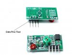
I have some RF communication modules for arduino and pickaxes (i think), got them on ebay: http://www.ebay.com/itm/New-RF-Wireless-Transmitter-and-Receiver-Link-Kit-Module-433Mhz-for-Arduino-DIY-/251191004511?pt=LH_DefaultDomain_0&hash=item3a7c268d5f

Is this what i need?
I have some 08M2 and some 18M2+.
Now how do i read the codes on my remotes, and after how do I reproduce them?

thanks.
 

nick12ab

Senior Member
That receiver should be fine.

There's more than one type of signal encoding the remotes can use. The easiest way to find this out is (unless it is already stated in some documentation) is to use a logic analyzer or scope on the output of the receiver module. If that is not possible, then experiment with use of serin and rfin. Alternatively build a PICAXE logic analyzer - it only needs to be single channel.
 

macsoft

Member
Good idea! I have a logic analyzer, and i've used it before to find out IR codes on infrared remotes. Is this similar? Where do i hook up the leads on the logic analyzer?
And once I found the codes, how do i transmit them in picaxe commands?
thank you.
 

nick12ab

Senior Member
Good idea! I have a logic analyzer, and i've used it before to find out IR codes on infrared remotes. Is this similar? Where do i hook up the leads on the logic analyzer?
I think the receiver is the device on the left and I can't see any markings on it to indicate which pin is which. If there is a pin marked 'VCC' then connect that to the 5V rail and if there is a pin marked 'GND' or 'VSS' then connect that to the 0V rail. If the remaining two pins aren't clearly marked to indicate which does what then connect the ground connection of the logic analyzer to the 0V rail and probe both terminals on the receiver while pressing buttons on the remote to see which is the output.

And once I found the codes, how do i transmit them in picaxe commands?
thank you.
It might be possible to use the rfout or serout command or it might not. You'll have to analyze the signals first.
 

macsoft

Member
Ok so i grabbed the RF receiver, hooked power to the VCC and GRD and hooked up my logic analyzer probes to the both contacts in the center.
I tried various 433 remotes and nothing.. :S
It is kind of weird to me there are to contacts for data..
on the ebay deal they have a link they say "tested with Arduino 1 wire" http://www.open.com.au/mikem/arduino/VirtualWire.pdf

This does not help me very much :S
Anyone?

thanks
 

manuka

Senior Member
Macsoft: 433 MHz devices & PICAXEs are made for each other. However it's essential that you start simply and provide the forum helpers with DETAILED pictures,code & schematics- we can not read your mind or visualise your workbench! Details of your RF environment may help too- you may be next door to a radio ham or shielded by ferro-cement etc.

FWIW I've found Chinese Dorji ASK offerings (~US$5 each) ideal for simple 433 MHz needs. See => http://www.picaxe.orconhosting.net.nz/dorjiask.pdf Stan.
 

macsoft

Member
Macsoft: 433 MHz devices & PICAXEs are made for each other. However it's essential that you start simply and provide the forum helpers with DETAILED pictures,code & schematics- we can not read your mind or visualise your workbench! Details of your RF environment may help too- you may be next door to a radio ham or shielded by ferro-cement etc.

FWIW I've found Chinese Dorji ASK offerings (~US$5 each) ideal for simple 433 MHz needs. See => http://www.picaxe.orconhosting.net.nz/dorjiask.pdf Stan.
Hello Manuka,

I don't really understand your problem, I posted a pic and link of the RF Modules , i've stated what picaxe chips i have to my disposal, and stated i have no circuit yet so no schematic or code. I would like to get to the circuit stage...
I also stated my RF environment: I have a 433 remote controlled alarm, and some remote controls 433 lights.

I would like 2 things: to read the RF codes on my 433 remotes, and a way to reproduce them with my picaxes.
i also have another type of rx tx 433 :
 

manuka

Senior Member
Sorry if I sounded terse- I'd meant it more as an alert! This forum gets endless "my circuit's all wonky" calls for help & unravelling the hazy woe can be tediously painful...

If you've yet no circuit or code then start REALLY simply & get to know issues that may arise. Have you a solderless breadboard & PICAXE programming cable etc? Battery supply? Are you familiar with the PICAXE Editor? If OK on these then check this.and perhaps ideas from this. I HIGHLY recommend folks making a general 433MHz band monitor first thing. See a Keymark/Spiriton approach =>http://www.picaxe.orconhosting.net.nz/433mon.jpg

Be aware that wireless house alarm devices may NOT use just simple serial,as they need security & robustness. Even some backyard weather stations adopt complicated protocols. Stan.
 

BeanieBots

Moderator
As stated by manuka, RF alarms often adopt code hopping techniques which would be way beyond the ability of a PICAXE to process These are typically 42 bits with 8 bits used to generate a 'random' number giving 256 34-bit numbers to sift through whilst checking for a valid code AND keeping the 'random' numers in sequence using the same 'random' generator on both Tx and Rx units.
Also, the bit pattern itself may be either regular, manchester or some other type of encoding.
Your best bet is to put the Rx on your logic analyser and get a series of data streams to analyse before you do anything else.
Without datasheets for modules you won't get far unless you are prepared to put in a lot of experimentation and risk destroying the modules by wrong connection.
NEVER buy modules unless the supplier provides clear datasheets. It's a total waste of money.

Alternatively, create your own RF protocol using in-built PICAXE commands such serin/serout. These can be made very robust using qualifyers and any bit stream length you like.
 

hippy

Ex-Staff (retired)
Ok so i grabbed the RF receiver, hooked power to the VCC and GRD and hooked up my logic analyzer probes to the both contacts in the center.
I tried various 433 remotes and nothing.. :S
Did you connect an aerial / antenna ?

You may be not seeing anything because the signal levels are too low for the Logic Analyser so it would be best to look with a scope.

It is possible that the modules are defective, we are second guessing what the connections are and there's no manual so it will be a challenge. What does the chip on the receiver board do ? If it's expecting data in a particular format then you won't get any output until you send data in that particular format.
 

Jeremy Harris

Senior Member
Decoding the RF protocols used by some of the commercial remote control systems isn't that easy, but it can (just) be done with a Picaxe. I recently decoded the HomeEasy protocol using a Picaxe and a 433MHz receiver just like the one pictured in your first post (see here: http://www.picaxeforum.co.uk/showthread.php?23007-HomeEasy-Byron-433MHz-RF-decoding-with-a-Picaxe). I had to use a 14M2, running at 32MHz, to do the job, so any faster/bigger Picaxe should do it OK. The problem is getting the Picaxe to run fast enough to be able to measure the pulse widths, something that meant I had to avoid using loops in the code and run a sequential series of fairly simple instructions to get the execution speed up.

For the code below I used a Picaxe 14M2 with the 433MHz receiver output connected directly to input C.2. I added an LED driven from output C.1 as a crude indicator that the receiver had picked up a signal that was roughly of the right type. The comments in the code should be self-explanatory. This receiver is designed to output a unique ASCII code sequence for anyone of the many thousands of different HomeEasy signals. My intention is to use this to feed some additional switch circuits that only respond to particular codes. The receiver does some basic error checking and incorporates some timing gates to try and reduce the possibility of spurious signals. The 433MHz receivers output a lot of garbage all the time they are powered up, from received noise and all the myriad of other 433MHz signals there are floating around, so this error checking is pretty essential if you want a reasonably reliable system.

You can find the code here (it's too long to post on this forum): http://sourceforge.net/p/opentrv/code-0/205/
 

Goeytex

Senior Member
Ok so i grabbed the RF receiver, hooked power to the VCC and GRD and hooked up my logic analyzer probes to the both contacts in the center.
I tried various 433 remotes and nothing.. :S
It is kind of weird to me there are to contacts for data..
on the ebay deal they have a link they say "tested with Arduino 1 wire" http://www.open.com.au/mikem/arduino/VirtualWire.pdf

This does not help me very much :S
Anyone?

thanks
The Data pins are tied together on the board and have the same signal. You must connect your Analyzer Probe to one of these pins and the probe ground clip to the ground pin point. You should see digital "noise" when power is applied and no RF signal is present. When a signal is present you should be able to see a distinct pattern of bits. This of course assumes that the signal is ASK or OOK modulated and that your logic analyzer is capable.

If the security system uses Manchester encoding (somewhat likely) you will need to use Picaxe chips that support RFIN/RFOUT ... or an encoder/decoder chip such as the NKM2401.

If it were me I would first set up a simple wireless link using 2 Picaxes, one for the receiver and one for the Transmitter. This will confirm operation of the devices. Manuka provided a link that shows how to do that. Rev Ed also has information/ diagrams that should also apply to your modules. There are also lots of posts here that you can search if you get stuck.
 
Last edited:

hippy

Ex-Staff (retired)
The Data pins are tied together on the board and have the same signal.
Though not always. Some have a digital and an analogue output signal and connecting to the wrong one doesn't show what one would expect.
 

Goeytex

Senior Member
Though not always. Some have a digital and an analogue output signal and connecting to the wrong one doesn't show what one would expect.
I was specifically referring to the module that the OP Provided a link for. ...Not all ASK RF receivers.

These modules abound on EBAY under various Chinese brands. All of these have the same pin outs which can easily be seen either by looking on the back of the module or of a photo on Ebay where provided. See Attached

Goey
 

Attachments

macsoft

Member
I've tried several combinations of probe connection, including, 1 probe to one of the pins, and the other to ground..
I'm using Saleae Logic analyzer, but on the program, i'm limited to 24Mhz samples? could this be the problem?
Has I have several of these chips, i've tried 3 of them with the same results..
 

Jeremy Harris

Senior Member
I was specifically referring to the module that the OP Provided a link for. ...Not all ASK RF receivers.

These modules abound on EBAY under various Chinese brands. All of these have the same pin outs which can easily be seen either by looking on the back of the module or of a photo on Ebay where provided. See Attached

Goey
These are identical to the one I'm using to decode the HomeEasy remote control data. As you rightly say, they are very commonly found on ebay etc. I think I bought mine from a Far Eastern supplier a year or so ago (maybe Seeed Studio?).

Anyway, I can confirm that as soon as you apply power and fit a short bit of wire as an aerial these things just spit out digital noise, until they lock on to a signal.
 

macsoft

Member
Well i didn't put any aerial yet, but I held the remotes way close.. I will try the aerial.
No thoughts about the the 24Mhz sample limitation on the Saleae Logic? Or it does not have nothing to do with the 433Mhz i'm trying to get?
 

macsoft

Member
Well i didn't put any aerial yet, but I held the remotes way close.. I will try the aerial.
No thoughts about the the 24Mhz sample limitation on the Saleae Logic? Or it does not have nothing to do with the 433Mhz i'm trying to get?
 

hippy

Ex-Staff (retired)
No thoughts about the the 24Mhz sample limitation on the Saleae Logic? Or it does not have nothing to do with the 433Mhz i'm trying to get?
The 24MHz is the rate at which the Saleae samples its data at so irrelevant to the 433MHz RF. The data rates over RF will be considerably lower than 433MHz and almost certainly below the sampling rate of the Saleae.
 

Jeremy Harris

Senior Member
Well i didn't put any aerial yet, but I held the remotes way close.. I will try the aerial.
No thoughts about the the 24Mhz sample limitation on the Saleae Logic? Or it does not have nothing to do with the 433Mhz i'm trying to get?
I monitored the output of an identical receiver to this using a much lower sampling rate USB 'scope, and got good data on pulse widths and timing. The thread I referenced earlier a 'scope image from the output of one of these receivers, like this:http://www.picaxeforum.co.uk/attachment.php?attachmentid=13302&d=1357823721 This image is of a data sequence from a HomeEasy remote transmitter signal as received by the 433MHz receiver.
 

macsoft

Member
ok the aerial did it for me.
I can now read it on Saleae

I have to analize it and write down all the timmings.

Now.. i want picaxe to send these codes.
Can i get away with on/off an output, or maybe pulse it? i've been sucessful with pulses at 32Mhz on IR remotes.
Ist this a good idea in this case? or maybe some serial out? Never tryed serial communication before.
I expect the TX would get the duration of the each pulse and convert it to 433 Mhz, right?
 

macsoft

Member
Decoding the RF protocols used by some of the commercial remote control systems isn't that easy, but it can (just) be done with a Picaxe. I recently decoded the HomeEasy protocol using a Picaxe and a 433MHz receiver just like the one pictured in your first post (see here: http://www.picaxeforum.co.uk/showthread.php?23007-HomeEasy-Byron-433MHz-RF-decoding-with-a-Picaxe). I had to use a 14M2, running at 32MHz, to do the job, so any faster/bigger Picaxe should do it OK. The problem is getting the Picaxe to run fast enough to be able to measure the pulse widths, something that meant I had to avoid using loops in the code and run a sequential series of fairly simple instructions to get the execution speed up.

For the code below I used a Picaxe 14M2 with the 433MHz receiver output connected directly to input C.2. I added an LED driven from output C.1 as a crude indicator that the receiver had picked up a signal that was roughly of the right type. The comments in the code should be self-explanatory. This receiver is designed to output a unique ASCII code sequence for anyone of the many thousands of different HomeEasy signals. My intention is to use this to feed some additional switch circuits that only respond to particular codes. The receiver does some basic error checking and incorporates some timing gates to try and reduce the possibility of spurious signals. The 433MHz receivers output a lot of garbage all the time they are powered up, from received noise and all the myriad of other 433MHz signals there are floating around, so this error checking is pretty essential if you want a reasonably reliable system.

You can find the code here (it's too long to post on this forum): http://sourceforge.net/p/opentrv/code-0/205/
Hey jeremy!
This seams really cool . way easier than i was going for: reading all the intervals on a logic analizer by eye...
How do you read the codes? do you serial them to the PC?
And reversing, when you want to send RF codes with a RX, how does it go?

thanks
 

Jeremy Harris

Senior Member
Hey jeremy!
This seams really cool . way easier than i was going for: reading all the intervals on a logic analizer by eye...
How do you read the codes? do you serial them to the PC?
And reversing, when you want to send RF codes with a RX, how does it go?

thanks
The plan is to read the codes (which are serial ASCII data) using other Picaxes that control lights, dimmers etc. I'm planning on using the HomeEasy remote controls to switch low voltage lighting, as HomeEasy/Byron don't sell low voltage switches, only mains powered ones. The codes could just as easily be read and used by a PC or any computer.

The protocols used by these remote control systems vary from one make to another, so although I've documented the HomeEasy/Byron protocol in the comments on that code, if you want to work out the protocol for other makes then you may have to resort to measuring pulse widths with a 'scope or logic analyser and then reverse engineering the code. Most use a form of Manchester encoding, where two pulses are used to define either a 0 or a 1. In the case of the HomeEasy code, they use combinations of long and short pulses, so that 64 transmitted pulses gives a 32 bit code. They also separate out each data packet with a long initial pulse, that's used to tell the receiver to expect data. I was helped by others who had already decoded the purpose of the individual groups of bits within the 32 bit sequence, so was able to concentrate on just getting the 32 bit binary number from the transmitted data. I'd suggest doing a web search for your particular make of remote unit. I found there were several home automation sites where people had already done a lot of the work in working out the protocols for some systems.

Transmitting the data via a 433MHz transmitter should be just a matter of reconstructing the received pulse train. The challenge is going to be doing this fast enough. I've not looked at it in detail, but suspect that the problem is going to be creating accurate pulse widths for the negative going pulses as well as the positive going ones. It may well be that the only way to do this is to use two output pins and gate them with external logic before feeding the result to a transmitter.
 

macsoft

Member
Playing with ways to transmit on a 08M2.
Trying pulsout..
THe picaxe manual says "Time is a variable/constant which specifies the period (0-65535) in 10us units(at 4MHz resonator)." So pulse pin,1 at 4Mhz should give me a 10us pulse, no?
Well i read 14us on the logic analyzer. But I can dial it up to 32Mhz and get 1.7 us. more than enough.
The transmuter works as easy as the receiver. just connect it to an output pin, power it, and it should transmit for as long as the pulse lasts...
Problem is.. i can pulse a 14us from the picaxe output, but when connected to the TX, and connecting the logic analyzer to the RX, the minimum RF pulse i can get is 60uS :S
This is very weird.. does the TX works slower than the RX? reading the signal from my light control remote, the shorter pulse from the sequence is 14uS. So the RX can get pulses that fast.
Why the hell can't I get a pulse at least as short as that on the TX?

Not that is helps me much right now, Can anyone identify the pattern on the image?


thank you
 

Jeremy Harris

Senior Member
You will probably find that there are critical timing issues with both the positive going pulse widths and the width of the gaps between them. The pulsout command can only specify the pulse width, not the width of the gap between pulses, and this will be critical to getting reliable data transmission. The main problem is that although you can control the pulse width (using pulsout) accurately, you cannot control the time between pulses directly, only indirectly by measuring the execution time of your code and then adjusting it to get the timing right.

What is the make of the remote control system that you're trying to use? The chances are that someone will have already done some work on analysing the protocol, if it is one of the fairly common household remote systems, which will be a great help. The sequence of pulses that you've shown seems pretty short to me. Usually these things transmit a code that is around 30 to 80 pulses long in total. For example, the HomeEasy/Byron protocol uses 64 pulses to transmit a 32 bit data sequence, plus the longer start pulse gap.
 

macsoft

Member
I can get the timing i need from the picaxe. if i plug the probe of the logic analyzer on the pickaxes output pin, i get the timing right. i can control the gaps with pauseus at 32Mhz, or, just pulsing an unused pin. The problem is that when i connect the pickaxes output pin to the TX, and i hook the probes to the receiver circuit, The TX pulses can't get as fast has the picaxe outputs them. at least not with pulsout.
Just for debug i tried to use pwmout to get shorter pulses (not minding the oscillation for now), and that way I can get very short pulses with the TX! so... what is going on here?

These remotes are brandless chinese ones..
 

Jeremy Harris

Senior Member
There will be a minimum pulse width for the transmitter/receiver pair, set by the transmission bandwidth. I was decoding a commercially available home automation remote control, that uses fairly wide pulses (typically 280µS high pulses separated by gaps of either 230µS or 1.2mS). I would hazard a guess that they picked these fairly wide pulses to get the best compromise between reliable transmission and excessive data burst length.

My best guess is that you may struggle to transmit pulses that are much shorter than about 100µS through a transmitter/receiver pair. I don't know for sure what the bandwidth of these modules is, but 10kHz would seem to be a reasonable guess. Others here have more experience with using them for more critical data transmission tasks, so may be able to shed more light on this.

I thought from your first post that you wanted to interface with your house alarm and lights? If so, then that's the protocol you need to decode. The lights may well use a protocol like the HomeEasy/Byron 32bit one, but I'd guess that the alarm might use something a fair bit more secure, and may be challenging to decode.
 

hippy

Ex-Staff (retired)
i can pulse a 14us from the picaxe output, but when connected to the TX, and connecting the logic analyzer to the RX, the minimum RF pulse i can get is 60uS :S
Most remote protocols will not be sending with pulses that short; pulses would normally be in the region of a few hundred microseconds.

In post #24 it is not clear what you are showing in the logic analyser trace; pulses sent from a PICAXE, pulses received from a remote control, or simply noise. Normally there will be some consistency in on and/or off periods for remote control data, and there is some consistency in post#24, but there's a lot that looks like noise rather than any obvious code.

There will probably be some stream of signals before the actual code data to condition the receiver for receiving the data and this may be what you are looking at. You should really look at what the remote is putting out to its RF transmitter module rather than trying to second guess it from what a receiver is receiving. Once you know what the transmitter puts out you can then check you are seeing the same on the receiver and can thenset about decoding it.
 

MartinM57

Moderator
When trying to decode unknown signals don't completely rely on the Saleae - you should also have a look at the signals with an oscilloscope to see what's really happening...the Saleae is giving you a digital representation of an analogue signal and may be hiding material things from you
 

macsoft

Member
When trying to decode unknown signals don't completely rely on the Saleae - you should also have a look at the signals with an oscilloscope to see what's really happening...the Saleae is giving you a digital representation of an analogue signal and may be hiding material things from you
THat is true Martin, i did check with a digital pocket oscilloscope, and the situation is the same :S
 

Jeremy Harris

Senior Member
THat is true Martin, i did check with a digital pocket oscilloscope, and the situation is the same :S
As a couple of us have said, the minimum pulse width you can get through one of these TX/RF links is probably greater than 100µS. You were trying to stuff pulses through that are shorter than that by a fair margin.
 

macsoft

Member
As a couple of us have said, the minimum pulse width you can get through one of these TX/RF links is probably greater than 100µS. You were trying to stuff pulses through that are shorter than that by a fair margin.
but if i can READ short pulses with the RX and if the remote sends this short pulses, AND if i can send very short pulses thru the TX with pwmout, we know the RX/TX can handle it.. what is the problem then?
 

Jeremy Harris

Senior Member
but if i can READ short pulses with the RX and if the remote sends this short pulses, AND if i can send very short pulses thru the TX with pwmout, we know the RX/TX can handle it.. what is the problem then?
The problem is the bandwidth of the transmitter/receiver pair. This bandwidth is quite modest, probably no better than 10 to 15kHz. Your logic analyser isn't, in all probability, reading the true pulse widths accurately, as you are seeing a reconstruction of the analogue output from the receiver.
 

Jeremy Harris

Senior Member
if so, then why with pwmout i can get short pulses and with pulsout i don't?
When you say you can get short pulses with pwmout, do you mean going through the TX/RX link?

The TX/RX link will have a pretty limited bandwidth, so it shouldn't be able to pass short single pulses accurately. If you're seeing short pulses through the TX/RX link, then I suspect that you may well be seeing artefacts on the logic analyser. A check with a 'scope will show what's really going on a lot more accurately than the logic analyser will, as that will show you the real signal, rather than a reconstituted one.
 

macsoft

Member
OK, probes on the RX. the picaxe is connected to the TX.
if i send pulsout pin,1 (4Mhz for example) i get it 60us on the RX side. if i probe the picaxe output pin i get 10us (ok 14us)
if i send a pwmout command (whatever frequency) i get pulses on the RX side as small as 2us.

a scope (crappy only, digital pocket one) does not tells me a different story.
 

Jeremy Harris

Senior Member
I suspect that what's happening is that the repetitive waveform from pwmout is affecting the way the link is responding. A repetitive waveform will also be reconstructed differently by any sampling measurement system. Sampling systems, be it a digital 'scope or a digital logic analyser, have limitations that affect how they reconstruct and display some signals.

There's no way that a 2uS pulse will really get through the link, because we know that these TX/RX have a smaller bandwidth than that (a 2uS pulse would require more than a 500kHz bandwidth on the link, for example), so what you're seeing with the continuous pwmout is almost certainly an artefact, possibly caused by the measurement devices automatically switching to over-sampling mode in the presence of a repetitive waveform (my USB 'scope does this, but luckily has an indicator to tell you when it's oversampling, so you can be aware that the display may be showing artefacts).

Sampling systems, like digital logic analysers and 'scopes, need to be used with care and due consideration for their limitations when looking at noisy signals where the bandwidth of the incoming signal may be close to, or exceed, the effective sampling frequency. I still have an old analogue CRT 'scope that I rarely use, but when I do it's almost always to do a cross check on something odd (almost always at high frequency/short pulse length) that's showing on the digital 'scope.

The bottom line is that the remote control system that you want to use will have fairly long pulse widths, so chasing this anomalous/spurious characteristic isn't getting you further forward in terms of understanding the pulse train from the alarm/light system you want to interface with. That will almost certainly use pulses that are at least a couple of hundred uS or so long as a minimum.
 
Top