Rev - Ed stepper motor half step possibility?

bfgstew

Senior Member
Can the Rev-ed unipolar stepper motor be half stepped using the circuit provide in maual 3 page 16?
I have it running fine at the moment using the toggle command but would like to get the steps down to an even finer resolution without the need for further circuitry.
Thanks in advance

Stewart
 

nick12ab

Senior Member
Since no-one's come up with an answer yet, I'll suggest that if you already own one you try doing this and see if it works.
 

bfgstew

Senior Member
DOH, sorry, been a long day, Yes I do have one, built and running, but I don't know how to get it to half step, that's my question?
Currently running it using

toggle pin 1
pause 10
toggle pin 2
pause 10
 

Paix

Senior Member
I suspect, that with two states to play with, that the only way from 1 1 is to 1 0 or to 0 1 which is where you are at the moment, so I believe that the answer to your question is that it is not possible.

I think that Nick was suggesting that it would be quicker for you, if you own one of the motors, to have a play and let us know the definitive answer to your question, as either no one apparently has both the motor and the answer to your question; at the moment. :)

All may not be lost. Someone with knowledge may yet make your day, but I'm not going to recommend that you hold your breath as it might be a long wait for the sort of answer that you are hoping for.

I'm currently waiting for a bunch of micro unipolar steppers to arrive from big C.
 

nick12ab

Senior Member
DOH, sorry, been a long day, Yes I do have one, built and running, but I don't know how to get it to half step, that's my question?
Currently running it using

toggle pin 1
pause 10
toggle pin 2
pause 10
Does it half-step if you only run this part?
Code:
toggle pin 1
pause 10
It's likely you would still have to toggle the second pin afterwards to complete the step.
 

hippy

Ex-Staff (retired)
I suspect, that with two states to play with, that the only way from 1 1 is to 1 0 or to 0 1 which is where you are at the moment, so I believe that the answer to your question is that it is not possible.
I am no motor expert but would have said the same. Two inputs gives only four coil activation states and for half stepping you need eight states.

I think you can do it with another two PICAXE output pins as you would then have complete control over every coil ( 16 states of which eight would be used ).
 

bfgstew

Senior Member
OK, thanks for the info chaps.
So how would I go about getting it to run, circuit wise, using 4 outputs from say an 08M2 and a darlington?
 

Paix

Senior Member
That would be a circular reference to your first post, Manual #3 page 16. The ULN2003A or ULN2803A Darlington arrays that Rev Ed sell. The latter will give you eight outputs so can be strapped as pairs for higher current handling.

The toggling would be arranged in a loop for continuous rotation.
 

Technical

Technical Support
Staff member
That's correct.
Generally unipolar have two of the 4 coils reversed simultaneously, as per your original circuit.
To half step you simply only switch one of the 4 coils at a time. So you need to be able to control all 4 individually.
 

bfgstew

Senior Member
Thanks for the pointers guys, appreciated.

So, just to make sure I have this correct, I can/could have the motor wired up like these?

ULN2003.jpgULN2803.jpg
 

bfgstew

Senior Member
I have been doing some further investigations and searches and came across Westaus55's tutorial, nice piece of work, but it has confused me further with regards to adding the current limiting resistors and the formula to get the correct rating (math was not my best subject), can someone help please.
Power supply is 12v 500mA Wall wart.
Motor is Rev-Ed unit and is unipolar with 150 ohms on coils
 

Paix

Senior Member
Let's see what we can do: Perhaps one of the forum stalwarts can advise about masking so that only pins C.1 and C.2 are affected by the Pins= command.

Code:
#Picaxe 08m2
' Hacked by Paix, Warning - untried & untested. I have no live stepper motor experience

' Rev Ed item GBX008
' Stepper Y129-5
' If you use the wires in the 6 pin connector in
' order the following program should cause rotation
' Black +12V
' White +12V
' Yellow output7
' Red output6
' Brown output5
' Orange output4


Symbol StepDelay = 200
forever:
do
  if pinC.3 = 1 then
    gosub forward
  else ' C.3 = 0 of course
    gosub backwards
  endif
loop ' forever

forward:
do
  if pinC.4 = 0 then
    exit
  endif
  for b1 = 0 to 6 step 2
    pins = b1 ' This should be two bits C.1 is LSB and  C.2 is MSB
    if pinC.4 = 0
      exit
    endif
    pause StepDelay
  next b1
loop ' forward
return

backward:
do
  if pinC.4 = 0 then
    exit
  endif
  for b1 = 6 to 0 step -2
    pins = b1
    if pinC.4 = 0 then
      exit
    endif
    pause StepDelay
loop ' backwards
return

Manual #3 page 16 refers. Use ULN2003A as shown.
As explained, the ULN2003A can be used to produce the inverted signal
signals required and saves you two Picaxe pins.
This is acomplished by connecting a 1k resistor between:
in2 and in6
in3 and in7

out6 and out7 are each pulled up to +5V (4.5V is you must) via a 1k resistor
Additionally:
out6 is connected to in1
out7 is connected to in4
in5 and out5 are unused (free to be used for something else)
All as shown on the page 16 diagram

The motor wire colours appear to be a bit contradictory between Manual #3 page16 and the, Tech Supplies,
item description,
so take care and read the spec. The coils are nominally 75 Ohm (160mA required from the Darlington/s)
each and so If you measure between two leads and get a figure near to 150 Ohm, then you are measuring two coils.
Identify the common connection for sanity and then get excited about the correct sequencing
– before you solder anything!

Suggestion: increads the delay period so that your eyes and brain can keep up with what is going on
and replace the four windings with four LEDs, each with a 100K current limiting resistor. When you
are happy with the sequence from the ULN2003A and have the common connection to the windings
of the motor identified, start looking at the sequencing.

I believe that Tech Supplies does mention that the wiring colours can vary between
suppliers/manufacturers.
 
Last edited:

bfgstew

Senior Member
Paix, I really do appreciate the time and effort you have put into your reply, but I do have the motor running as per the manual perfectly, what I am after is for it to do half stepping, which is shown in Westaus55's post, but I am at a loss as to how to get it wired correctly.
 

bfgstew

Senior Member
Thanks e, I have read that and has helped, westaus55's tutorial has given me this code

Code:
[color=Black]Main: [/color][color=Blue]let [/color][color=Purple]dirsC [/color][color=DarkCyan]= [/color][color=Navy]%10111[/color]
[color=Blue]FOR [/color][color=Purple]w0 [/color][color=DarkCyan]= [/color][color=Navy]1 [/color][color=Blue]TO [/color][color=Navy]400 [/color][color=Green]; Select any number of steps based upon
;magnitude of total rotation required[/color]
[color=Blue]GOSUB [/color][color=Black]Lstep[/color]
[color=Blue]NEXT [/color][color=Purple]w0[/color]
[color=Blue]PAUSE [/color][color=Navy]5000[/color]
[color=Blue]FOR [/color][color=Purple]w0 [/color][color=DarkCyan]= [/color][color=Navy]1 [/color][color=Blue]TO [/color][color=Navy]400[/color]
[color=Blue]GOSUB [/color][color=Black]Rstep[/color]
[color=Blue]NEXT [/color][color=Purple]w0[/color]
[color=Blue]PAUSE [/color][color=Navy]5000[/color]
[color=Blue]GOTO [/color][color=Black]Main
Lstep: [/color][color=Purple]b2 [/color][color=DarkCyan]= [/color][color=Purple]b2 [/color][color=DarkCyan]+ [/color][color=Navy]1[/color]
[color=Blue]GOTO [/color][color=Black]Step2
Rstep: [/color][color=Purple]b2 [/color][color=DarkCyan]= [/color][color=Purple]b2 [/color][color=DarkCyan]- [/color][color=Navy]1[/color]
[color=Black]Step2: [/color][color=Purple]b2 [/color][color=DarkCyan]= [/color][color=Purple]b2 [/color][color=DarkCyan]& [/color][color=Navy]%00000111[/color]
[color=Blue]LOOKUP [/color][color=Purple]b2[/color][color=Black], [/color][color=Blue]([/color][color=Navy]%00010010[/color][color=Black], [/color][color=Navy]%00010000[/color][color=Black], [/color][color=Navy]%00010001[/color][color=Black], [/color][color=Navy]%00000001[/color][color=Black], [/color][color=Navy]%00000101[/color][color=Black], [/color][color=Navy]%00000100[/color][color=Black], [/color][color=Navy]%00000110[/color][color=Black], [/color][color=Navy]%00000010[/color][color=Blue])[/color][color=Black], [/color][color=Purple]b3[/color]
[color=Blue]let [/color][color=Purple]pinsC [/color][color=DarkCyan]= [/color][color=Purple]b3[/color]
[color=Blue]pause [/color][color=Navy]100[/color]
[color=Blue]RETURN[/color]
Which works in simulation, now do I need any resistors to the motor to the darlington? I hate releasing the magic smoke!
 

Paix

Senior Member
What happens if three coils are energised, will that offset the position? In isolation, with a travelling zero, it should become evident when you got the zero in the right right sequence to step, albeit perhaps at a reduced holding power.

Then it is a suck it and see case of popping one of those sequences interleaved in the original and if the behaviour seems good, then you can seek the slot for the second of the new sequences. If you got the single zero's stepping correctly, then having identified the start with regard to the original sequence, then it's only the first slot that you should need to identify.

Yes, i do seem to have changed my tune a little, based on my slightly modified perception.

I'm off out now, but will inevitably look back later in the evening to see what's going on. :) Hopefully I make a degree of sense?

Your original code sequence is dependent upon the coil connections and vice versa, so depending on the coil connections the zero may not move linearly left to right in your code in quite the way we might expect . . . I think (perhaps too much)!

= = = A problem solved can be a lesson learned or a myth dispelled = = =
 

bfgstew

Senior Member
Success!

We now have my motor running at half steps, brilliant, the trade off is it runs slower, obviously, but the accuracy is superb, I can now get steps on my macro rail down to 0.005mm, which is pretty impressive, and if I really wanted to, I could single step it with westaus55's code to get it even lower probably down to 0.0005mm, but that would be for ultra macro stuff and I don't have the equipmant for that. Now to merge the two codes and alter the circuit on my board so I can run it on my controller, rather than breadboard.
Thanks once again guys for your valued input and guidance, much appreciated.

Stewart
 

bfgstew

Senior Member
Once the circuit and coding have been completed and fully tested I shall post it up (sometime next week), hopefully with westaus55's very informative tutorial folks can get these powerful little motors singing and dancing for them without serious circuitry.
 

oracacle

Senior Member
Success!

We now have my motor running at half steps, brilliant, the trade off is it runs slower, obviously, but the accuracy is superb, I can now get steps on my macro rail down to 0.005mm, which is pretty impressive, and if I really wanted to, I could single step it with westaus55's code to get it even lower probably down to 0.0005mm, but that would be for ultra macro stuff and I don't have the equipmant for that. Now to merge the two codes and alter the circuit on my board so I can run it on my controller, rather than breadboard.
Thanks once again guys for your valued input and guidance, much appreciated.

Stewart
OK, now you have peaked my interest. What pitch lead screw are you using, are you moving the camera or object to be imaged.

also it interests me as to why you think you donve the equipment to make use of that smaller step, it may suprise you how small your DOF is
http://www.tirpor.com/macro/macro_DOF.htm
i would take the maths on that site and run it through your own calculator/excel (i use excel on my phone ATM, handy for carrying with me). i was suprised how small my DOFs were even just using a home made close up filter (cant afford a proper macro lense, maybe soon though). dont forget that each slice need an ideal 50-70% overlap, i have had some shot that were 0.22mm thick while on a midle f-stop,

My new rail should be done in the next couple of months depending on money, but I sent the chassis designs off for machining yesterday, I have a zero backlash ball screw and nut, a suprising strong nema 17 bi-polar stepper and micro step controller so far. some enitial testing shows it may well be able to lift more than the the 4kg i orignally specified (camera and kit lense ways 2.5kg, pro camera can be more than 1kg body only).

look forward to seeing the outcome of your project
 

bfgstew

Senior Member
Well, I whimped out of altering my stepper drive, the work involved to alter the PCB and coding just didn't justify the results to be perfectly honest. I can drive my macro rail down to 0.01mm which is plenty small enough for my subject matter, I could alter the actual drive train to get the increments smaller, but as I said, I am happy enough with it as it is.
I did learn a BIG lesson though, when designing something, think, plan, think again, check all options, think again, plan, have another think and if all options are covered go for it. I seem to rush in thinking I know I have everthing right, but end up changing it after completion.
I did get the stepper to half step, which is great, something new I have learnt, thanks to westaus55's super tutorial. I have several other steppers, bipolar and unipolar, large and small to play with, so I have plenty of stuff to build a rig up to design and test drive units, but that is for another day.
Thanks to all for your contributions.

Stewart
 

Paix

Senior Member
That's a bit of a shame, but as per Eclectic's post #21, how about posting the code that you have for the benefit of others treading a similar path?
 

bfgstew

Senior Member
That's a bit of a shame, but as per Eclectic's post #21, how about posting the code that you have for the benefit of others treading a similar path?
Basically I used the code that is in westaus55's tutorial.

But on another note, I did come into pocession of some hefty hardware, namely an industrial labelling unit, complete power supply unit with 70v, 24v,12v and 5v outputs, several stepper drive cards and all housed in a rather large rack unit. Now my logic is that this is going to be used to drive my large 4.6A steppers for my CNC machine that I am currently building, but the drive cards are built to drive steppers and couldn't waste an opportunity to see if I could rig a board up to drive another smaller unipolar stepper. so after hours of googling and checking the cards I sussed out how to get it to drive. They have the L297 driving two L2603, with, and this caused the headache, one quad exlusive OR gate logic chip and a schmitt trigger AND gate, all very confusing, but as I said I did suss it out. A signal wire to the ENABLE input via an ouptocoupler, a signal wire to the STEP input and a signal wire to the DIRECTION input, a 5v VCC input and 24v input for the motor all coupled up to a little 08M2, a few lines of code to simply get the motor to step was failry simple, after altering the phase wires to the motor and once I got the right I had a go at using PWM for the first time, and got the motor spinning faily rapidly without too much fuss, the PWM is still a bit alien to me but once I get the rig completely finished I will use it to test code effeciency, half stepping and even chopping, so looking forward to learning more stuff.Sorry this is not entirely Picaxe related, but wanted to share my experiences and see if any one has some knowledge of using PWM and if they can point me in the direction.

Happy stepping folks
 

oracacle

Senior Member
i maybe be of a little help on the pwm from, i bit of test with my controller and stepper showed that even though i could get hte spindle speed righ on up there it became easier to stall the motor

i will continue to use the 'for pulsout next' routine for my rail, it is much slower but allows much greater speed.

i havent tested with different duty cycles or step sizes as of yet but i cant see it making a huge difference
 

bfgstew

Senior Member
I changed my mind, I owed to westaus55 and myself to do this, when someone has gone to great lengths to prove something and gives time and effort freely it's the least I could do.
I have altered my wiring (spoilt the layout of PCB though) on the board and have the motor running, sort of, as I think the coding will need some fine tuning, as the motor jitters ever so slightly and has little torque, so something I shall work on through the coarse of the day, will keep you posted.

Stewart
 

oracacle

Senior Member
i just thought i would give you some info i had gained in past few hours

some of the work i have done with the few little bi-polars i have did seem to show the same thing with little torque unless connected to a micro step controller.

the controller also give much better holding torque as it doesn't keep the coil fully energised nor fully de-energised but part energised saving power and heat.
also depending on the controller it makes it easier to upgrade both the motor and controller - the controller i am using needs 2 power feeds and 3 wires to control direction, enable and rotation.
 

bfgstew

Senior Member
Well I have managed it, to a certain degree. Altered the board so I now have 4 double inputs into the ULN2803 and 4 double outputs to the stepper, fairly simple to do and not to much mess made. The hard bit was getting the coding and math correct, which is still in need of work. I am using the half step method on the forward travel and have got it to move my macro rail down to 0.005mm/step which is superb, the trouble is on reverse as I want rapid reversal I have it in full step mode, I just can't get the variables to match at the moment, but I will suss it out later, and when I have it working correctly I shall post code for others to utilize as they wish.
 

bfgstew

Senior Member
I know have it running exactly, well to be honest, better than I had planned. After several hours of madness trying to sort the math out on this, it came to me in a flash and now works like a dream. I now have full travel to 36mm (limitation of DVD rail) but can step it down to not 1/2 step, but 1/4 step. Trialed it with a D.T.I. attached to rail frame and with set points entered at 1mm travel and 400 stacks it jogged its way nicely and precisely for 1mm and 400 stacks then returning to its origin without a hitch.

I will post code up later tonight for your perusal.

Thanks go to Westaus55 for posting an informative tutorial on stepper driving.
 

bfgstew

Senior Member
As promised the code that runs my macro rail to 1/4 stepping = 0.0025mm per step!!!!!!!

Code:
SETZEROUP:								;start of stepping
	do
		gosub GKP                                 ; keypad routine omitted for clarity
			if key_value = 10 then goto mini    ; drive stepper forward
			if key_value = 12 then goto mini1   ; drive stpper backwards
			if key_value = 0 then goto SLACK    ; confirm in zero start position and to start main run
		loop


mini:
	let dirsC = %11110000                 	;defines output pins for stepper
	let pinsB = %00101011                 	;an easier way for a button press on keypad
		serout lcdpin,baud,(255,%011)       ; lights indicating LED
			do
				let pinsC = %10100000   ;step sequence
			pauseus 200                   ;pause time between steps, have found this is the lowest I can go
				let pinsC = %10010000
			pauseus 200
				let pinsC = %01010000
			pauseus 200
				let pinsC = %01100000
			pauseus 200
				loop until COL2 = 1      ; if button pressed on keypad it stops run
					serout lcdpin,baud,(255,%001) ; turns LED off and illuminates another
				goto SETZEROUP
					
mini1:                             ;same as above but in reverse
	let dirsC = %11110000
	let pinsB = %00101011
		serout lcdpin,baud,(255,%011)
			do
				let pinsC = %01100000
			pauseus 200
				let pinsC = %01010000
			pauseus 200
				let pinsC = %10010000
			pauseus 200
				let pinsC = %10100000
			pauseus 200
				loop until COL2 = 1
					serout lcdpin,baud,(255,%001)
				goto SETZEROUP
					
SLACK:                                  ;short sequence of steps to take slack out of rail drive train
	let dirsC = %11110000
		for b12 = 1 to 2
			let pinsC = %01100000
		pauseus 200
			let pinsC = %01010000
		pauseus 200
			let pinsC = %10010000
		pauseus 200
			let pinsC = %10100000
		pause 10
			next b12


RUNMACRO:	
	let w5 = w5 * 1000      ;adjustable pause time between shots and steps
	let w21 = w20 * 400 / w22       ;calculation to get number of steps to do per stack
	let w26 = w22	                    ;allows 2 variables to be used as one is used as countdown
		serout lcdpin,baud,(254,1)
			pause 30
				serout lcdpin,baud,(254,128,"MACRO RAIL RUNNING")
				serout lcdpin,baud,(254,148,"STACK SET = ",254,160,#w22)
  				serout lcdpin,baud,(254,212,"STEPS LEFT = ",254,225,#w26," ")
  			let pinsB = %00101011
				
			
steprun:					;this part essentially sets camera mirror lock up	
	
	serout lcdpin,baud,(255,%101)
		high CAMERA
	pause 500
		low CAMERA
	pause RAILPAUSE
		high CAMERA : high FLASH
	pause 500
		low CAMERA : low FLASH
			serout lcdpin,baud,(255,%011)
				let dirsC = %11110000
steprun2:                        ; this is westaus55's code to do halfstepping
	for w27 = 1 to w21         ;w21 is the number of steps to do
		b2 = b2 + 1
		b2 = b2 & %00000111
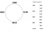
			lookup b2,(%00100000,%01100000,%01000000,%01010000,%00010000,%10000000,%100000000,%10100000),b3
			pinsC = b3
				inc w18 ;allows w18 to be used as a counter later in code
				inc w25 ;same again, used as a counter
			if w27 = w21 then goto steprun3
		next w27
	goto steprun2
	
steprun3:
	dec w26
		serout lcdpin,baud,(254,225,#w26," ")
			if w26 = 0 then goto returns
			if COL1 = 1 then goto abort
		goto steprun
		
abort:                                    ;if keypress is activated the run is aborted and using w18, it returns to zero
	low READY_LED
		serout lcdpin,baud,(255,%010)
			serout lcdpin,baud,(254,1)
		pause 30
			serout lcdpin,baud,(254,128," OPERATION ABORTED")
			serout lcdpin,baud,(254,192," RETURNING TO ZERO")
			serout lcdpin,baud,(254,148,"    POSITION")
		pause 250 
			let dirsC = %11110000
			let w18 = w18 / 8
		do
			let pinsC = %10100000
		pauseus 200
			let pinsC = %10010000
		pauseus 200
			let pinsC = %01010000
		pauseus 200
			let pinsC = %01100000
		pauseus 200
			dec w18
				loop until w18 = 0
			pause 30
				serout lcdpin,baud,(255,%000)
			pause 30
		goto INIT			
			
			
returns: ;when reaches end of run uses w25 to count back to zero
			
	low READY_LED
		serout lcdpin,baud,(255,%011)
		serout lcdpin,baud,(254,1)
	pause 30
		serout lcdpin,baud,(254,128," RETURNING TO ZERO")
		serout lcdpin,baud,(254,192,"    POSITION")
	pause 250
		let dirsC = %11110000
		let w25 = w25 / 8
	do
		let pinsC = %10100000
	pauseus 200
		let pinsC = %10010000
	pauseus 200
		let pinsC = %01010000
	pauseus 200
		let pinsC = %01100000
	pauseus 200
		dec w25
			loop until w25 = 0
				pause 30
			serout lcdpin,baud,(255,%000)
		pause 30
	goto INIT     ; run complete and goes back to start
Any questions, just ask.

Stewart
 
Top