Remote height adjuster

marzan

Senior Member
Hello.

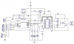
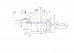
I have a threaded rod with a geared motor attached. I want to send the nut to 4 positions. I was thinking of using ADC to check where the nut is by using a 10K 10 turn potentiometer, that will be geared accordingly, as the shaft needs to make 350 turns from position 1 to position 4. the commands to move will come via wireless remote I have started the schematic while I wait for the components to arrive. Can anyone see anything that`s not right or something that should be included? I want to get a prototype made so can get into the coding when the parts arrive. The picaxe chip will be providing PWM and a tri state pin to the motor driver:


autoheight33.jpg
 
Last edited:

hippy

Technical Support
Staff member
It seems to me it should work. The only issue is of ADC mapping to 'nut position'. With 1024 ADC resolution and 350 turns that's less than 3 ADC bits per turn, or 120 degree of turn resolution.

I haven't analysed the circuit itself.
 

RexLan

Senior Member
350 turns on a fine thread will give a 10" or longer rod.

I would use something as simple as logic and micro switches or a logic wire that will have a voltage change along the way like trains use.

I made an automatic roof vent opener for my greenhouse and used a gear motor on a rod with a tab that ran on a rail to hit limit switches on either end and reverse itself. I used a simple time function to position it at various points along the way and two 55 Ic's to make an intervalometer that sampled the temperature every 10 minutes to decide it it needed to open or close more. Still working after 25 years + use.
 

goom

Senior Member
Or maybe use a stepper motor and tell it to turn a specific number of rotations. No position sensing required, except perhaps for a micro-switch for initial positioning during program startup.The accuracy that you want for the positioning will influence the optimum solution.
 

geezer88

Senior Member
Back in the "old days", satellite antennas were positioned with a screw jack to allow using multiple satellites. The screw had a simple toothed wheel on it and either a hall effect sensor, or a reed switch, or a photo interrupter were used to count fractions of a turn. The controller simply was trained to a particular satellite and it's corresponding count. Fancier system used a "home switch", usually a microswitch at one extreme as a zero.

In your case, the method used might depend on your accuracy needs, the speed of positioning needed, the frequency of use, and the environmental conditions. A little more information along these lines might make the choice pretty easy.

Unless you need very high precision or extreme speed, the PicAxe should be a fine controller.

tom
 

marzan

Senior Member
Or maybe use a stepper motor and tell it to turn a specific number of rotations. No position sensing required, except perhaps for a micro-switch for initial positioning during program startup.The accuracy that you want for the positioning will influence the optimum solution.
I am trying to bring dog agility into the 21st century :) . The idea is to have all the jumps automatic. The worst part of training dogs is the constant height changing of the jumps /tables which is done manually.
I had originally decided to use steppers. I decided against it for several reasons. A lot more circuitry.Higher voltage. It would be an open loop system so it would be more coding and time to setup because it would have to start from a datum every time you switched it on. I am looking into a coarser thread to cut down on the number of turns needed, but I have to balance that with the power of the gear motor that`s going to drive it.
Another question I have for people a lot smarter than me. If you make a double sided PCB that uses RF would you take out the ground plane ? reading up on a few sites say its possibly not a good idea. I have no clue as to the conventions of double sided PCB`s. Do you use pwer on one side, ground on the other, and signal however you get the tracks tidy? or does that give you more capacitance? I just want to make sure that the Dorji module and the motor play nice when it is finished.
Marz.
 

BESQUEUT

Senior Member
Why not connecting the 10k to +V to have a full range divider ?
And what is the (unconnected) 2K resistor for ?
 

marzan

Senior Member
Why not connecting the 10k to +V to have a full range divider ?
And what is the (unconnected) 2K resistor for ?
Ooops! The 2k resistor is connected to V+ (6v) Using 2k so I do get the full range of ADC for the 5V PICAXE.
 

flyingnunrt

Senior Member
Hi mate, we do agility too, In fact we are off to a comp now for the weekend (3.5 hour drive)
You could use some IR interrupter switches at the various heights and just drive the saddles to the various locations then if they get bumped they could be made to drive back to the desired height automatically,
a bit like a servo for example.
 

marzan

Senior Member
Hi mate, we do agility too, In fact we are off to a comp now for the weekend (3.5 hour drive)
You could use some IR interrupter switches at the various heights and just drive the saddles to the various locations then if they get bumped they could be made to drive back to the desired height automatically,
a bit like a servo for example.
Yer theres dozens of ways to do this,but as you know the less working parts the better, as the jumps do get flattenned by dogs and handlers. My end coal in this is to have a system using the dogs microchip in a database to save their times and also set the jump/table height. Thats a long way off.
Marz.
 

BESQUEUT

Senior Member
Ooops! The 2k resistor is connected to V+ (6v) Using 2k so I do get the full range of ADC for the 5V PICAXE.
Very dangerous !
If there is an "open circuit" in the pot, Picaxe is directly connected to +6V...
And the reading will not be linear with pot rotation...
For example, if pot is 1/5 to ground, it is 2K and readADC will be 3V/5V*1024=614 !

Very unusual. Any advice from specialists ?
 

marzan

Senior Member
Very dangerous !
If there is an "open circuit" in the pot, Picaxe is directly connected to +6V...
And the reading will not be linear with pot rotation...
For example, if pot is 1/5 to ground, it is 2K and readADC will be 3V/5V*1024=614 !

Very unusual. Any advice from specialists ?
I thought I had it right, but it seems not. What value would I use to get the full ADC ? or do you put a resistor vetween the voltage divider andthe ADC pin?
 

BESQUEUT

Senior Member
I thought I had it right, but it seems not. What value would I use to get the full ADC ? or do you put a resistor vetween the voltage divider andthe ADC pin?
Simply connect pot to V+ Picaxe (after D1, not 6V), and remove 2K resistor.
 
Last edited:

RexLan

Senior Member
Over-thinking it ..... simple time on or off with basic calcs or lookup from a table of locations will position it at any location more than likely to within a MM.

You could add two micros for safety backup to prevent over/under shoot in the event of a Picaxe failure.

Why not directly drive two FET's configured as high side switches ... simplify.

Or relays if using AC gearmotor.
 
Last edited:

marzan

Senior Member
I have now made a pcb that seems to do what I want, so have started to write the program.
I am using a 14m2.
There are 4 pins (c.1 to c.4) that will be used to get the required height to set the jumps to.
C.0 is the voltage divider that checks the actual height of the jump.
B.1 sets the motor travel up or down.
B.2 enables the motor.

I was doing ok ( I think ) until I got this error:

endif
^
Syntax error on line 36 at/before position 8

Error: Endif without If

It is probably something obvious but I cant see it. Here is the code:
Code:
symbol redled = b.4
symbol bluled = b.3
symbol enable = b.2
symbol motordir = b.1
symbol inputval = b2
symbol hcheck = b3


getinput:
	do
		let inputval = pinsc & %00011110
		select case  inputval
		case 1
		goto heightmove
		case 2
		goto heightmove
		case 4
		goto heightmove
		case 8
		goto heightmove
		endselect
	loop
	
heightmove:
	inputval = inputval * 64
	readadc c.0, hcheck
		if hcheck > inputval then high motordir : goto go_up
		else low motordir : goto go_down
		endif
		
go_up:
	do
		high enable
		readadc c.0, b4 
			if b4 > inputval then goto getinput
			endif
	loop


Go_down:
	do
		high enable
		readadc c.0, b4 
			if b4 < inputval then goto getinput
			endif
	loop
Anyone have any ideas?
Thanks in advance.

Marz
 

premelec

Senior Member
put the structure like this

if b4 > inputval then
goto getinput
endif

[and read up on the hazards of GOTOs... :) ]
 

hippy

Technical Support
Staff member
"IF condition THEN GOTO label" is a one-line IF statement which does not require a subsequent ENDIF.

It should be, as a single line IF statement -

Code:
IF condition THEN GOTO label
or, as a multi-line block statement -

Code:
IF condition THEN"
  GOTO label
ENDIF
or, with a colon to keep the IF-THEN part separate from the GOTO statement -

Code:
IF condition THEN : GOTO label
ENDIF
 

hippy

Technical Support
Staff member
GOTO's do not necessarily make for bad code but code can often be restructured to make the program flow easier to follow. For example -

Code:
Go_down:
	do
		high enable
		readadc c.0, b4 
			if b4 < inputval then goto getinput
			endif
	loop
could alternatively be coded as -

Code:
Go_down:
  high enable
  do
    readadc c.0, b4 
  loop until b4 < inputval
  goto getinput
 

premelec

Senior Member
I would suggest writing in more subroutines - GOSUB or CALL getinput then takes you back to where you did the CALL perhaps inside a loop... whatever suits you... :) There's a long thread a few weeks back on some of the troubles of GOTOs - but it's whatever works for you...

getinput:
'do stuff
RETURN
 

inglewoodpete

Senior Member
inglewoodpete: had some poles that had some sort of height control setup all hooked up to a picaxe.
check old posts probably about a year or two ago.
http://www.picaxeforum.co.uk/showthread.php?11762-PICAXE-forms-part-of-robotic-body-of-semi-living-art&p=92475&viewfull=1#post92475
Thanks for digging that one up, flyingnunrt! You must have a good memory. We used an L298 H-bridge for the geared motor on that job.

The original positioning feedback mechanism used a nichrome wire and wiper potentiometer but the nichrome spanned about 2 metres and had a resistance of about 32 ohms. +5v was switched across the nichrome using a MOSFET for just brief periods when reading the position. Due to the current that the wire would draw (~150mA), it heated and slackened if left powered for long periods. I eventually went to ultrasonic position measurement, which was as accurate as the nichrome wire/ADC but much simpler to assemble and much more reliable. Keep in mind that the movement was 2 metres though!

For marzan's project there are many possibilities, including using a nichrome wire and wiper with a much lower supply voltage (say, 100mV or less) and a rail-to-rail Op-Amp to get a 0-5v output range suitable for the PICAXE ADC input. This would also minimise any noise intrusion, due to the low impedances involved.
 

marzan

Senior Member
Thanks for digging that one up, flyingnunrt! You must have a good memory. We used an L298 H-bridge for the geared motor on that job.

The original positioning feedback mechanism used a nichrome wire and wiper potentiometer but the nichrome spanned about 2 metres and had a resistance of about 32 ohms. +5v was switched across the nichrome using a MOSFET for just brief periods when reading the position. Due to the current that the wire would draw (~150mA), it heated and slackened if left powered for long periods. I eventually went to ultrasonic position measurement, which was as accurate as the nichrome wire/ADC but much simpler to assemble and much more reliable. Keep in mind that the movement was 2 metres though!

For marzan's project there are many possibilities, including using a nichrome wire and wiper with a much lower supply voltage (say, 100mV or less) and a rail-to-rail Op-Amp to get a 0-5v output range suitable for the PICAXE ADC input. This would also minimise any noise intrusion, due to the low impedances involved.
I have taken the simple option, using a 10 turn 10k pot geared to the worm drive which moves the height of the jump. I need a max 0f 400mm movement, so with a 1/2" UNC thread it gives me a touch over 200 turns. The reduction boxes/motors are rated at 375 R.P.M. so roughly 40 seconds from top to bottom. Most of the time you would go through the range 100mm at a time. For training purposes a few mm either way won`t matter. Now I just need to wait until all the parts arrive so the first prototype can be tested before moving on to make 30 more.
Just a question for the technical people on the forum. 100nf decoupling capacitors....is there any difference using poly ones or ceramic/tantalum SMD ? Also if using a max. of 12v, would 16v ones be fine?
Thanks.
Marz.
 

techElder

Well-known member
Ceramic capacitors are fine for decoupling power supply pins.

Always go higher voltage on caps rather than lower voltage ... from experience.
 

marzan

Senior Member
I have a prototype made up that has a coupe of issues. This is the photos and schematic:

agility schem.jpgproto1.jpg

I have 2 issues. Firstly there seems disproportionate voltage drop across the L293d. 7.2V going in, and only 3.4V at the motor.(P.S the diode in the schematic to drop the voltage to the picaxe has been replaced with a Vreg as I have gone higher than 6V)
Secondly when I press a button to get it to move it goes for half a second in one direction then stops. If I press any button again it goes for half a second in the other direction. i`m not sure if its a code problem or a circuit one.
Here is the code:
Code:
[color=Blue]symbol [/color][color=Black]redled [/color][color=DarkCyan]= [/color][color=Blue]b.5
symbol [/color][color=Black]bluredled [/color][color=DarkCyan]= [/color][color=Blue]b.4
symbol [/color][color=Black]greenled [/color][color=DarkCyan]= [/color][color=Blue]b.3
symbol [/color][color=Black]enable [/color][color=DarkCyan]= [/color][color=Blue]b.2
symbol [/color][color=Black]motordir [/color][color=DarkCyan]= [/color][color=Blue]b.1
symbol [/color][color=Black]inputval [/color][color=DarkCyan]= [/color][color=Purple]b2[/color]
[color=Blue]symbol [/color][color=Black]hcheck [/color][color=DarkCyan]= [/color][color=Purple]b3[/color]
[color=Blue]symbol [/color][color=Black]hval [/color][color=DarkCyan]= [/color][color=Purple]b4[/color]
[color=Blue]symbol [/color][color=Black]checkingheight [/color][color=DarkCyan]= [/color][color=Purple]b5[/color]


[color=Blue]debug[/color]

[color=Black]getinput:
      hval [/color][color=DarkCyan]= [/color][color=Navy]0
      [/color][color=Blue]low [/color][color=Black]enable
            [/color][color=Blue]do
                  let [/color][color=Black]inputval [/color][color=DarkCyan]= [/color][color=Purple]pinsc [/color][color=DarkCyan]& [/color][color=Navy]%00011110
                  [/color][color=Blue]select case  [/color][color=Black]inputval
                  [/color][color=Blue]case [/color][color=Navy]16
                  [/color][color=Blue]goto [/color][color=Black]buttona
                  [/color][color=Blue]case [/color][color=Navy]2
                  [/color][color=Blue]goto [/color][color=Black]buttond
                  [/color][color=Blue]case [/color][color=Navy]4
                  [/color][color=Blue]goto [/color][color=Black]buttonc
                  [/color][color=Blue]case [/color][color=Navy]8
                  [/color][color=Blue]goto [/color][color=Black]buttonb
                  [/color][color=Blue]endselect
            loop
            [/color]
[color=Black]buttona:
            hval [/color][color=DarkCyan]= [/color][color=Navy]200
            [/color][color=Blue]high [/color][color=Black]redled
            [/color][color=Blue]wait [/color][color=Navy]1
            [/color][color=Blue]low [/color][color=Black]redled
            [/color][color=Blue]goto [/color][color=Black]heightmove
buttond:
            hval [/color][color=DarkCyan]= [/color][color=Navy]50
            [/color][color=Blue]high [/color][color=Black]bluredled
            [/color][color=Blue]wait [/color][color=Navy]1
            [/color][color=Blue]low [/color][color=Black]bluredled
            [/color][color=Blue]goto [/color][color=Black]heightmove
            
buttonc:
            hval [/color][color=DarkCyan]= [/color][color=Navy]100
            [/color][color=Blue]High [/color][color=Black]greenled
            [/color][color=Blue]wait [/color][color=Navy]1
            [/color][color=Blue]low [/color][color=Black]greenled
            [/color][color=Blue]goto [/color][color=Black]heightmove
            
buttonb:
            hval [/color][color=DarkCyan]= [/color][color=Navy]150
            [/color][color=Blue]high [/color][color=Black]redled
            [/color][color=Blue]high [/color][color=Black]greenled
            [/color][color=Blue]wait [/color][color=Navy]1
            [/color][color=Blue]low [/color][color=Black]greenled
            [/color][color=Blue]low [/color][color=Black]redled
            [/color][color=Blue]goto [/color][color=Black]heightmove
            
            
heightmove:
      
      [/color][color=Blue]readadc c.0[/color][color=Black], hcheck
            [/color][color=Blue]if [/color][color=Black]hcheck [/color][color=DarkCyan]< [/color][color=Black]hval [/color][color=Blue]then high [/color][color=Black]motordir : [/color][color=Blue]goto [/color][color=Black]go_up
            [/color][color=Blue]else low [/color][color=Black]motordir : [/color][color=Blue]goto [/color][color=Black]go_down
            [/color][color=Blue]endif
            [/color]
[color=Black]Go_up:
  [/color][color=Blue]high [/color][color=Black]greenled
  [/color][color=Blue]high [/color][color=Black]enable
  [/color][color=Blue]do
    readadc c.0[/color][color=Black], checkingheight 
  [/color][color=Blue]loop until [/color][color=Black]checkingheight [/color][color=DarkCyan]> [/color][color=Black]hval
  [/color][color=Blue]low [/color][color=Black]greenled
  [/color][color=Blue]goto [/color][color=Black]getinput


Go_down:
  [/color][color=Blue]high [/color][color=Black]redled
  [/color][color=Blue]high [/color][color=Black]enable
  [/color][color=Blue]do
    readadc c.0[/color][color=Black], checkingheight 
  [/color][color=Blue]loop until [/color][color=Black]checkingheight [/color][color=DarkCyan]< [/color][color=Black]hval
  [/color][color=Blue]low [/color][color=Black]redled
  [/color][color=Blue]goto [/color][color=Black]getinput[/color]
Feel free to critique the code. Always trying to find more efficient ways to do things.

Marz
 

SAborn

Senior Member
I can not work out your supply to VSS of the 293. it should be wired direct to the 5V+ rail, as VSS is the logic power supply for the chip.

All up the 293 looks a little wierd in its wiring to me, but it is late here and im tide so perhaps someone can pickup on what im missing.
 

marzan

Senior Member
Sorry Pete. Forgot to explain.vss is wired to 5v. The transistor and associated stuff is to make the input tri state. That way if I needed I could use the enable pin to pwm the motor.that way if it overruns the position I can slow it down first.nhopethat makes sense.

Marz
 

marzan

Senior Member
I have done some searching. there are two versions of this chip. DRV8837DSGT and DRV8838DSGT the first uses PWM, the second the normal enable and direction. These use MosFets so should be less voltage drop. seem ideal for small brush motors. Have ordered some to play with.

Marz.
 
Top