Afternoon all, just had a chat with the kind people at picaxe and they have advised to ask you intelligent people on the forum for advise.
I have built a working replica of 'Orac' the super computer from Blakes 7, which is switched on via a 'key' (a reed switch and a magnet in a box) when the box is put on top of the case the reed switch is activated and it comes to life.
Sensor 16 led chaser and 2 sets of 8 red leds flash and the main 'Brain' pulsates, and makes a operating noise, also when you move your hand over a certain area it plays a random phrase from the show as if it is talking to you....
This is all working brilliantly and no problems, put the 'key' on and it works, take the key off and it stops.
One thing that would make it spot on, is when the key is removed it makes a sort of dying sound.
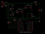
The easiest way I can think of doing this is to not have the 'key' as the main on/off switch, but as a sensor to detect when it is activated.
When the key is not there the voltage to the reed switch is 0v so can loop until it detects a voltage and then flick a relay (to activate the whole lot) then keep looping round working and sensing the voltage, if it is 0v then the key has been removed and it can activate the 'dying' sound and then reset and wait for the key to be put back on.
Now to the question.
The whole lot is running from the standard 3xAAA batteries and can power the whole lot for a few days on one set of batteries.
On the shop site they have TR99-6VDC-SB-CD Miniature DPDT 5A Relay.... But the technical team do not know what the holding voltage of the relay is?
I googled the data sheet and it says voltage 6v and pull in voltage is 75%, which makes it 4.5v , but it does not give a holding voltage.
The chips work down to about 2.5v and do not want the whole thing to switch off too soon.
Has anybody used these relays? or any advice on something that would work better ... Ideally they would hold above 2v and it would all work fine...
Thanks in advance as doing a chip order and can put some of these on if they will do the job....
I have built a working replica of 'Orac' the super computer from Blakes 7, which is switched on via a 'key' (a reed switch and a magnet in a box) when the box is put on top of the case the reed switch is activated and it comes to life.
Sensor 16 led chaser and 2 sets of 8 red leds flash and the main 'Brain' pulsates, and makes a operating noise, also when you move your hand over a certain area it plays a random phrase from the show as if it is talking to you....
This is all working brilliantly and no problems, put the 'key' on and it works, take the key off and it stops.
One thing that would make it spot on, is when the key is removed it makes a sort of dying sound.
The easiest way I can think of doing this is to not have the 'key' as the main on/off switch, but as a sensor to detect when it is activated.
When the key is not there the voltage to the reed switch is 0v so can loop until it detects a voltage and then flick a relay (to activate the whole lot) then keep looping round working and sensing the voltage, if it is 0v then the key has been removed and it can activate the 'dying' sound and then reset and wait for the key to be put back on.
Now to the question.
The whole lot is running from the standard 3xAAA batteries and can power the whole lot for a few days on one set of batteries.
On the shop site they have TR99-6VDC-SB-CD Miniature DPDT 5A Relay.... But the technical team do not know what the holding voltage of the relay is?
I googled the data sheet and it says voltage 6v and pull in voltage is 75%, which makes it 4.5v , but it does not give a holding voltage.
The chips work down to about 2.5v and do not want the whole thing to switch off too soon.
Has anybody used these relays? or any advice on something that would work better ... Ideally they would hold above 2v and it would all work fine...
Thanks in advance as doing a chip order and can put some of these on if they will do the job....