Registering that Pin is High

sailgene

Member
Hello Group.

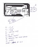
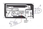
I've got a problem that seems simple enough. I've built this cat feeder which uses an 08M chip to essentially turn the feeder on and off every 12 hours. The feeder uses a pvc drum which rotates 360 degrees (filling at one point and dumping at another). I've had a problem with timing of the drum rotation as it does not always run at the same speed when chunks of cat food get caught in the cracks. And so picking "x" number of seconds for the rotation did not work well over time.

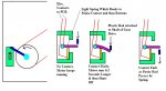
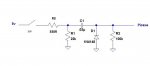
So, I decided to add a switch which is simply a set of contact points - activated by a lever on the drum. When activated, the switch sends power to pin 3 of the chip. My program tells the motor that if pin 3 goes high, run it for a few more seconds to get the drum in the right position for the next feeding and then turnoff. This usually works fine but at times, the contact does not seem to be registered and the motor keeps turning or prematurely stops. The problem may be that when the contacts are made (contact lasts about .5 second), the program is currently ignoring that particular command which again tells the motor to stop. But I was figuring the program is cycling pretty fast through the "away" portion of the code (see below) that 1/2 second of contact time would be plenty.

This is the area of code as written:

AWAY:

HIGH 2 'RUN MOTOR TO TURN FEEDER DRUM
IF PIN3=1 THEN TURNOFF 'IF PIN 3 GOES HIGH, TURN OFF MOTOR VIA TURNOFF ROUTINE
IF PIN3=0 THEN AWAY 'KEEP RUNNING MOTOR IF PIN 3 IS LOW

TURNOFF:

PAUSE 6200 'WAIT 6.2 SECONDS FOR CONTACTS TO DISENGAGE AND RESET DRUM
LOW 2 'STOP MOTOR
GOTO CLOCK 'BEGIN TIMER FOR NEXT 12 HOUR CYCLE


CLOCK:

FOR B1 = 1 TO 200 'START COUNTER
PAUSE 60000 'PAUSE FOR 60 SECONDS PER CYCLE (200 CYCLES = 3 HOURS 20 MINUTES)
NEXT B1
FOR B2 = 1 TO 200 'START COUNTER
PAUSE 60000 'PAUSE FOR 60 SECONDS PER CYCLE (200 CYCLES = 3 HOURS 20 MINUTES)
NEXT B2
FOR B3 = 1 TO 200 'START COUNTER
PAUSE 60000 'PAUSE FOR 60 SECONDS PER CYCLE (200 CYCLES = 3 HOURS 20 MINUTES)
NEXT B3
FOR B4 = 1 TO 119 'START COUNTER
PAUSE 60000 'PAUSE FOR 60 SECONDS PER CYCLE (119 CYCLES = 1 HOUR 59 MINUTES)
NEXT B4
PAUSE 50000 'PAUSE FOR 50 SECONDS MORE
GOTO AWAY 'START OVER AND BEGIN RUNNING MOTOR UNTIL PIN 3 GOES HIGH AGAIN

Any ideas for better code would be appreciated. PS: The contacts are clean and work fine. Pin 3 has a pull-down resistor.

Thanks.

Gene Darby
 
Last edited:

jtcurneal

Senior Member
If pin 3 has a PULL DOWN resister, It will always be low and the motor will keep running.

Joel

forget about this post. I reread your post
 
Last edited:

sailgene

Member
On-Off Circuit

I've attached a pic of the circuit (switch). A 5 volt wire leads to the spring and a second wire leads back to pin 3 of the chip. When the blue lever contacts the spring, it pushes it down onto a brass piece which closes the circuit to pin 3. After about .5 second, the lever lets go of the spring and it bounces back up losing contact, opening the circuit. Hmmm, wonder if the bouncing part could be a problem??
 

Attachments

erco

Senior Member
AWAY:

HIGH 2 'RUN MOTOR TO TURN FEEDER DRUM
wait4switch:IF PIN3=0 THEN wait4switch 'KEEP RUNNING MOTOR IF PIN 3 IS LOW

PAUSE 6200 'WAIT 6.2 SECONDS FOR CONTACTS TO DISENGAGE AND RESET DRUM
LOW 2 'STOP MOTOR

CLOCK:
etc...

That's about as simple as it gets, basically a pared-down version of your program. If it's not working, then suspect something in your switches and/or wiring.
 

sailgene

Member
wait4switch?

Hello Erco.

Could not follow your explanation. I'm assuming that "wait4switch" is not a picaxe command. And I still need to tell the picaxe to watch for Pin 3 going high.

As for the wiring, the circuit works perfectly most of the time. I'll watch the contacts more closely to verify they're closing the circuit.

Sorry if I seem a llittle ignorant on this.

Gene
 

MartinM57

Moderator
I'm assuming that "wait4switch" is not a picaxe command
No - it's a label :D

Agree with watching the contacts carefully - I'd also put a pause 1000:sertxd("...started") near the top of the program, connect your programming lead and watch the F8 terminal window in the programming editor ... you may be getting transients from your motor that is resetting the PICAXE
 

erco

Senior Member
XLNT call, Martin! Resetting could well be the culprit here. Plus, you just taught me the sertxd command, thank you very much. I'm just starting with PicAxes, though I've been a Basic Stamp user for many moons.

Gene: Use 3 delta filter caps on your motor. Are you using a relay to switch your motor on/off? Flyback diode? Seperate motor/PicAxe power supplies? You'll do the right thing! :)
 

sailgene

Member
Watching

No - it's a label :D

Agree with watching the contacts carefully - I'd also put a pause 1000:sertxd("...started") near the top of the program, connect your programming lead and watch the F8 terminal window in the programming editor ... you may be getting transients from your motor that is resetting the PICAXE
Thanks for your help and from everyone else.

Gene Darby
 

sailgene

Member
Mosfet to switch motor on/off, diode across motor leads. 12v supply to motor. Power to Picaxe through same supply but via 7805 circuit. Caps on 7805 circuit but none on the motor. Plus, until I added this switch, it ran perfectly, except for the timing....
Thanks again.

Gene
 

Goeytex

Senior Member
@Gene

When I suggested a schematic I meant a complete schematic that includes everything, not just the switch. With a complete schematic that includes all components and component values, folks can analyze the entire circuit and make more informed suggestions.

If the problem began with adding the switch then it is likely that the switch is introducing a transient. Have you limited current to the switch ? Or from the switch to the Picaxe ? If so then how ?
 

sailgene

Member
Schematic

@Gene

When I suggested a schematic I meant a complete schematic that includes everything, not just the switch. With a complete schematic that includes all components and component values, folks can analyze the entire circuit and make more informed suggestions.

If the problem began with adding the switch then it is likely that the switch is introducing a transient. Have you limited current to the switch ? Or from the switch to the Picaxe ? If so then how ?
Sorry about the lack of a complete schematic. I have a shot of the pcb but I'd have to add labels to all components (standard 7805 circuit with caps to power picaxe), pull down resistors and a mosfet powered by the picaxe (with resistor) to switch on the motor. The new switch is powered from the same 7805 circuit. I am sharing the power to the picaxe with the power to the contact switch. Maybe that's the problem? The slight drop in power when it's shared between the input power pin and pin 3? Would that be enough of a drain to reset the picaxe?

If so, then I need to separate the power sources. Or is there another way around this?

Thanks.
 
Last edited:

inglewoodpete

Senior Member
You can get away with 1 power supply easily. However, you will need to design and wire up the circuit correctly to minimise interference from the motor circuit into the logic circuit.

Without a circuit (even a scanned pencil sketch) and a photo of your wiring or PCB we can't help much more than that.
 
Last edited:

Goeytex

Senior Member
If you are not willing to take the time to draw up and post a schematic then there is not much that anyone can do to help
except make wild guesses. And you did not answer my question about current limiting to the switch. So I'll make my
wild guess.

You have the switch tied directly to 5V with possibly a pull a down resistor of unknown size on the input pin. The switch bounces when activated . There may be motor noise on the switch wires.

1. Try adding the attached circuit. It eliminates switch bounce,limits current and provides a neat little positive
pulse to the Picaxe.

2. Use common /standard methods to eliminate motor noise.

3. Use a 100nf Decoupling CAP on the Picaxe V+ Pin
 

Attachments

Last edited:

sailgene

Member
Per your request

Okay, I'm attaching a rough copy of the circuit. You should know that I've had no problems with the motor noise impacting the picaxe. Until I added this "switch", the circuit has worked perfectly for about a year. But the "switch" does vibrate (making multiple contacts in closing the circuit) as I used a spring as one contact point. So perhaps the vibrating contact fouls up the picaxe (sending multiple "highs" and "lows" to pin 3) and could be solved by dampening the spring action.

Gene Darby
 

Attachments

Goeytex

Senior Member
Gene,

Decyphering a layout graphic is difficult. A schematic is better, but.....

It looks like you may have the spindle switch shorting 5v to ground which would indeed
reset the Picaxe as the actuator passes the switch. If the squiggly lines mean no
connection the you are ok. But I cant tell by the layout without components.

You need a pull down resistor on the Picaxe Input for the switch.

Make the changes I show in the attached modified graphic and get back to us.
 

Attachments

Last edited:

sailgene

Member
No, the squiggly line does mean no connection. R5 is the 10k pulldown resistor as I noted in the notes. So we're back to my theory that the spring part of the switch vibrates, causing multiple high-lows on pin 3.
 

MartinM57

Moderator
But multiple highs-lows shouldn't make a difference if the code is as erco's above

HIGH 2 'RUN MOTOR TO TURN FEEDER DRUM
wait4switch:IF PIN3=0 THEN wait4switch 'KEEP RUNNING MOTOR IF PIN 3 IS LOW

PAUSE 6200 'WAIT 6.2 SECONDS FOR CONTACTS TO DISENGAGE AND RESET DRUM
LOW 2 'STOP MOTOR

...the first detected high causes a jump to the 6.2s pause, so it doesn't matter if the switch bounces or is clean
 

sailgene

Member
Thanks. That makes me feel better about my bouncy spring issue. It's working right now so unfortunately, it's an intermintent problem and maybe just a glitch. Thanks again.

Gene Darby
 

inglewoodpete

Senior Member
Some feedback on the circuit board design.

You will see that the motor ground, via the MOSFET, shares a conductor with the ground or 0v connection with the PICAXE. This is not a good idea as spiky current flowing through the motor will result in (small) changes in the voltage applied to the 0v pin on the PICAXE. At times, this can reset (restart) the PICAXE.

A better design would would be to connect the 0v return from the MOSFET to the 0v copper trace coming from the bottom left of the picture. Obviously, disconnect the MOSFET from the rightmost 0v track in the picture at the same time.

Peter
 
Last edited:

sailgene

Member
Spikes in Current

Hi Peter.

Thanks for the tip. But are you saying that the extra distance is what makes the difference? As 0V is still common to all of the components, I guess by routing the Mosfet 0V to the lower left would simply add 4 or 5" of space between it and the Picaxe 0V connection. It would still be a common source. Is that what you mean?

Thanks.

By the way, before adding my switch, I simply used the picaxe to activate the motor twice a day for a set number of seconds. It never failed to work properly. My only problem cropped up when I programmed the picaxe to stop the motor after the switch was activated. And again, it's been an intermittent (sp) problem. Right now, it's been working perfectly for the last 10 or so cycles - about 5 days.

But thanks again. If distance is an issue, I'll take your advice when building my next circuit.

Gene
 

SAborn

Senior Member
The serial input pin has only 1 resistor and is listed as 10K going to ground, shouldnt this be a 10K to ground and then 22K to serial input.

A 0.1uf decoupling cap across 5v and ground at the picaxe would be good also.

10uf cap prior to the LM-7805 is a bit too small for my liking, and would go at least to 330uf, as my testing with input filter caps on a cro has proven to me less then 330uf noise gets through and even more so when using motors.

The track size for the 5v+ rail looks reasonably light in a few spots and wonder how well it has etched, and if there is high resistance causing a voltage drop when the switch is actuated.
 

SAborn

Senior Member
Any ideas for better code would be appreciated. Gene Darby
Not a big improvement, but just another way of doing the timing loop that makes it a bit simpler and uses less code lines and reduces the number of variables used, maybe not important here but often we need to save as many variables as we can.

Also added some "symbols" as its a good idea to get use to using them even in small simple programs like this.

Code:
#picaxe 08m

symbol Y =		b1
symbol hour_counter = 	b2

symbol limit_switch =	pin3
symbol motor =		2


AWAY:

	HIGH motor 	                                'RUN MOTOR TO TURN FEEDER DRUM
	IF limit_switch = 1 THEN TURNOFF 	       'IF PIN 3 GOES HIGH, TURN OFF MOTOR 
	IF limit_switch = 0 THEN AWAY 	                'KEEP RUNNING MOTOR IF PIN 3 IS LOW

TURNOFF:

	PAUSE 6200                              'WAIT 6.2 SECONDS FOR CONTACTS TO DISENGAGE
	LOW 2                                      'STOP MOTOR
	GOTO CLOCK                              'BEGIN TIMER FOR NEXT 12 HOUR CYCLE	

CLOCK:

	FOR Y = 0 TO 59                         'START COUNTER
	PAUSE 60000                              'PAUSE FOR 60 SECONDS PER CYCLE
	NEXT Y

	inc hour_counter                            'Increase Hour Counter by 1

	if hour_counter = 12 then                 'Check total of Hour Counter
	hour_counter = 0		'If 12 hours has passed reset the counter to zero
	goto away                                     'Go and feed the pussy
	endif
	
	goto clock                         'If 12 hours has not passed loop back to clock
 
Last edited:

sailgene

Member
Code Improvement

Not a big improvement, but just another way of doing the timing loop that makes it a bit simpler and uses less code lines and reduces the number of variables used, maybe not important here but often we need to save as many variables as we can.

Also added some "symbols" as its a good idea to get use to using them even in small simple programs like this.

Code:
#picaxe 08m

symbol Y =		b1
symbol hour_counter = 	b2

symbol limit_switch =	pin3
symbol motor =		2


AWAY:

	HIGH motor 	                                'RUN MOTOR TO TURN FEEDER DRUM
	IF limit_switch = 1 THEN TURNOFF 	       'IF PIN 3 GOES HIGH, TURN OFF MOTOR 
	IF limit_switch = 0 THEN AWAY 	                'KEEP RUNNING MOTOR IF PIN 3 IS LOW

TURNOFF:

	PAUSE 6200                              'WAIT 6.2 SECONDS FOR CONTACTS TO DISENGAGE
	LOW 2                                      'STOP MOTOR
	GOTO CLOCK                              'BEGIN TIMER FOR NEXT 12 HOUR CYCLE	

CLOCK:

	FOR Y = 0 TO 59                         'START COUNTER
	PAUSE 60000                              'PAUSE FOR 60 SECONDS PER CYCLE
	NEXT Y

	inc hour_counter                            'Increase Hour Counter by 1

	if hour_counter = 12 then                 'Check total of Hour Counter
	hour_counter = 0			'If 12 hours has passed reset the counter to zero
	goto away                                     'Go and feed the pussy
	endif
	
	goto clock                                     'If 12 hours has not passed loop back to clock
Thanks for the superior code. I love these chips but am still a little basic (pardon the pun) when writing code. Haven't yet messed with symbols and it looks like I'm quite alone in that department. But your time counter is so much more simple than mine. Thanks again.
 

sailgene

Member
Actually, the etching came out very clean. As for the 22k to serial input, you may be referring to the idea that I'm programming the chip on the board. I'm not. I instead put in an 8-pin socket and simply remove the chip each time I play with the programming. Again, it's worked quite well, before I added the switch. So I don't believe motor noise has been the problem.

But thanks again for all your help and advice.

Gene Darby
 

inglewoodpete

Senior Member
The effects of back-emf on electronic circuits.

Hi Peter.

Thanks for the tip. But are you saying that the extra distance is what makes the difference? As 0V is still common to all of the components, I guess by routing the Mosfet 0V to the lower left would simply add 4 or 5" of space between it and the Picaxe 0V connection. It would still be a common source. Is that what you mean?

Thanks.
Gene
There are differences between a circuit diagram and a working circuit with a motor or other interrupted inductor.

When you look at the circuit diagram, you see 5v, 12v and 0v lines - all looks sweet! The PICAXE switches the MOSFET on and the motor runs: nothing could be simpler. Not so.

On your circuit board, you have the 0v connection to the PICAXE linking back via the top trace to the regulator and your power source. However, the 0v return path for the motor also shares the same conductor (the PCB track across the top of the board).

When the motor turns, its commutator will switch the armature coils first one way and then in reverse. When an inductor is switched in and out of a circuit, its magnetic field collapses quite suddenly, generating voltages many times the supply voltage. Voltages in the order or 100 to 150v are quite common for a 12 volt motor. The resistance of the PCB trace between the MOSFET source and the 0v connection of the voltage regulator is not zero - it is probably a few milliohms or possibly more.

What happens when the motor produces a back-emf spike of 100v across its terminals? It induces a substantial current back through the circuit that it is connected to. This high current pulse causes voltages to be induced across each part of the return circuit: its wires, the MOSFET, the PCB tracks, the voltage regulator's smoothing capacitors and the power supply.

Part of the 100v spike will appear across the PCB trace that is shared with the PICAXE's 0 volt leg. At times the back-emf from the motor, across the shared PCB trace, will be sufficient to cancel the current required to run the PICAXE (or any electronic circuit). As a result, the PICAXE will restart and you will be left wondering why. Except you now know why;)

And you know why you need to keep the 0v return paths for the PICAXE and the motor separate: so the motor commutator noise or back-emf does not interfere with the operation of the electronics.
 

sailgene

Member
0V

There are differences between a circuit diagram and a working circuit with a motor or other interrupted inductor.

When you look at the circuit diagram, you see 5v, 12v and 0v lines - all looks sweet! The PICAXE switches the MOSFET on and the motor runs: nothing could be simpler. Not so.

On your circuit board, you have the 0v connection to the PICAXE linking back via the top trace to the regulator and your power source. However, the 0v return path for the motor also shares the same conductor (the PCB track across the top of the board).

When the motor turns, its commutator will switch the armature coils first one way and then in reverse. When an inductor is switched in and out of a circuit, its magnetic field collapses quite suddenly, generating voltages many times the supply voltage. Voltages in the order or 100 to 150v are quite common for a 12 volt motor. The resistance of the PCB trace between the MOSFET source and the 0v connection of the voltage regulator is not zero - it is probably a few milliohms or possibly more.

What happens when the motor produces a back-emf spike of 100v across its terminals? It induces a substantial current back through the circuit that it is connected to. This high current pulse causes voltages to be induced across each part of the return circuit: its wires, the MOSFET, the PCB tracks, the voltage regulator's smoothing capacitors and the power supply.

Part of the 100v spike will appear across the PCB trace that is shared with the PICAXE's 0 volt leg. At times the back-emf from the motor, across the shared PCB trace, will be sufficient to cancel the current required to run the PICAXE (or any electronic circuit). As a result, the PICAXE will restart and you will be left wondering why. Except you now know why;)

And you know why you need to keep the 0v return paths for the PICAXE and the motor separate: so the motor commutator noise or back-emf does not interfere with the operation of the electronics.
Maybe I'm missing something here: The motor's 0V is connected directly to the N-channel Mosfet's output, not the pcb trace. My diagram may be confusing as I didn't draw the half circle over the trace area from the mosfet to the motor's ground. The motor's 12V supply is connected to the trace. Am I still messed up here?
 

inglewoodpete

Senior Member
Maybe I'm missing something here: The motor's 0V is connected directly to the N-channel Mosfet's output, not the pcb trace. My diagram may be confusing as I didn't draw the half circle over the trace area from the mosfet to the motor's ground. The motor's 12V supply is connected to the trace. Am I still messed up here?
Yes, to quote you, you're still messed up. Perhaps a bit extreme. I'd say you're not understanding what the whole circuit is yet.

The connection between the motor and the drain of the MOSFET forms just a part of the 0v return path. I described the complete path previously: "its (the motor's) wires, the MOSFET, the PCB tracks, the voltage regulator's smoothing capacitors and the power supply" The current pulse from the back-emf of the motor will travel this whole path. The path includes the PCB tracks, the longest one shares the return current from the PICAXE.
 
Last edited:

sailgene

Member
Yes, to quote you, you're still messed up. Perhaps a bit extreme. I'd say you're not understanding what the whole circuit is yet.

The connection between the motor and the drain of the MOSFET forms just a part of the 0v return path. I described the complete path previously: "its (the motor's) wires, the MOSFET, the PCB tracks, the voltage regulator's smoothing capacitors and the power supply" The current pulse from the back-emf of the motor will travel this whole path. The path includes the PCB tracks, the longest one shares the return current from the PICAXE.
Messed up I am, but for the final time, my circuit works. It may not be correct and in the future I'll try and do better. I appreciate everyones help and ideas but sometimes the "help" gets almost too personal and I then regret asking for it in the first place. I'm going to go way now. Thanks again.

Gene Darby
 

sailgene

Member
Well, I finally figured out the problem. I was gazing over the Basic Commands manual when I came across the issue of Switch Bouncing. Turns out that this was my problem. I added a couple of lines of code to my program and the picaxe now works perfectly. Just wanted to let everyone know of this issue. Thanks.
 

westaust55

Moderator
Thank you for reporting back even though after some time.

Yes.virtually all switches can suffer from contract bounce and if the PICAXE and program is fast enough (ie a short/tight program loop) then it can detect several bounces as switch closures.
For most programming purposes using a command such as PAUSE 5 is sufficient.
If a COUNT command is used to time pulses over a specified period then clearly not possible to add a PAUSE commend so a small value capacitor between the input and ground will work as you found.
 
Top