Reed switch advise

Jarubell

Senior Member
Been a while, but I see free time in my future so I'm looking at a small project to monitor my fuel oil tank. I'm would like to find some magnitic reed switches that I could stack and install a magnet epoxyed to the level indicator inside the plastic lens. I'm hoping that that would give me a point level indication that then I would of use my PICAXE and AXE033, hmm, maybe two PICAXE and learn how to get them talking.

What type of reed switch would one suggest I look at? I see lots online but unsure what would be better for me.

Thanks,
James
 

MartinM57

Moderator
...magnitic reed switches that I could stack and install a magnet epoxyed to the level indicator inside the plastic lens
Picture please. The level indicator in my tank is a transparent (well, it was when new) vertical pipe outside the tank that is T'ed into the outlet with a "pull switch" that you have to pull to get the oil level in the pipe to reflect that level in the tank - a safety feature to stop all the oil draining out the tank if the pipe comes off.

That scenario would stop your idea working (in terms of measuring the level when unattended), but maybe your tank is different.

I'm sure this has been discussed before here - try a search (or wait for Ec to turn up)

EDIT1 : mines a bit like http://www.bes.co.uk/products/077.asp
EDIT2 : try a google with "oil tank oil level" - there's a few ways of doing it commercially that might be worth trying to "PICAXE" (although it does seem like quite a challenge)
 
Last edited:

Reloadron

Senior Member
If you want to go about this using reed switches there are manufacturers like Hamlin and also Hermetic Switch who manufacture what I think you are looking for. I also seem to remember a Coto Switch. They are distributed by most electronic parts houses. That or any home improvement store should sell door switches (magnetic) that can be gutted.

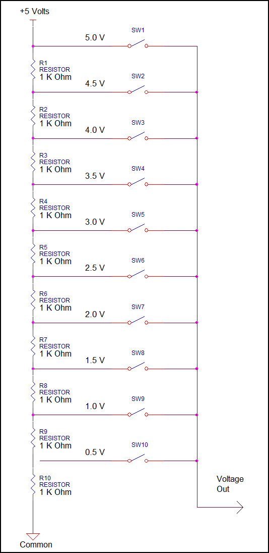
Given a choice I would make a long perf board and mount the switches spaced equally (however many you want). I would incorporate the switches with a simple resistor network. Think variable resistor where the switches are the wiper. One end of the string is +5 volt and the other is common. Each switch closure will provide a voltage out proportional to the level in the tank. This makes for a nice simple 3 wire system providing an analog output voltage. That voltage is fed into the A to D of your PIC. That eliminates the need for a pile of DI channels being used.

I would also, as mentioned, consider Hall Effect Sensors but if you want to go the reed switch route I would think about resistor ladder logic in a sense.

I should also mention when dealing with a fuel oil tank make sure anything electrical is well isolated from the oil and make sure the enclosure is not sensitive to fuel oil. Spark (even tiny spark) in fuel oil tank and things get real ugly real fast. :) Matter of fact I would think about enclosing switches or Hall Sensors in a stainless tube. Then use a floating donut magnet.

Ron
 
Last edited:

Jarubell

Senior Member
MartinM57, I have something simular to http://www.ksentry.com/documents/D-Cut.pdf and I'll be looking into hall sensors next. I know there are commercial available units that strap on but where's the fun in that.

Ron, I was thinking just what I think you are saying, lining up the sensors on a board attaching it to the OUTSIDE of the glass indicator. Sidenote, thank you for bring up the fuel oil+ Spark= no fun, I would never do such a silly install but it does need to be mentioned. My electronic skills are low and I'll have to look into variable resistor idea, however, I think with only having the one target passing by each senser, that idea might not work in this case.

Thanks guys, I'm off to discover Hall Sensors.

James
 

SAborn

Senior Member
I had a play with a fill sensor out of a Fisher and Paykel washing machine a while ago and think it would work well for this application.

The problem is if you can get your paws on one secondhand in your location.

I done a small report on using one here.......
http://ozelecforum.com/viewtopic.php?f=6&t=460

I was able to read 10mm hight changes very easy with a picaxe, and think it would be a easy cheap solution the your needs.
 

MartinM57

Moderator
..."Calibration: Consists of 3 pieces. Outer plastic piece, inner plastic piece, and a piece of paper in between" :D

Are you thinking of a line of Hall effect sensors (continuous reading) or just one (low level alarm)? Might be expensive to have many, you'll have to work out how to interface to the PICAXE, a a bit laborious to make and wire up and I'm not sure how you would get a continuous reading i.e. would the magnet always be sensed by one sensor?
 

Jarubell

Senior Member
SAborn, what was the range of that sensor?

MartinM57, I was thinking about multiply sensors for multiply points of level. I am now thinking of hall sensors and was gong to look into the maximum range of a hall effect transducer, which seems interesting. As of now, I have really no clue about cost. Im just starting to look at my options.

Thanks guys!
 

SAborn

Senior Member
I am not sure on the full range, what is the vertical depth of your tank.

If you are interested in going this way than i will do some tests, but not prepared to waste time if you are not really that interested.
 

Reloadron

Senior Member
When I get home from work today I'll post what I had in mind as to resistor logic. It is pretty simple and straight froward. Not actually using a pot but along those lines. Like 10 EA. of small 1 K Ohm resistors in series and the switches used as taps. Only a single switch is closed at any one time.

Being new here I assume I need to host the image off site and I can't do that from here at work. :(

I also like Pete's idea as to using pressure. Great way to go if you can get the pressure transducer.

Ron
 

Jarubell

Senior Member
NP SAborn, ~120cm.

Reloadron, I too like the pressure transducer setup but i'll have to try to locate one ( one compatible with the oil) and find a process connection to connect it. As for the resistor logic idea, if you have time that would be great.

James
 

Reloadron

Senior Member
Hi James

OK, here is what I had in mind using reed switches. Let's see if I can post an image. Didn't know I could just upload, learning curvr at work. :)


OK, if getting the image up worked what we have is a simple series string of resistors. We have 10 switches for 10 taps. When the top switch is closed you would have 5 volts going to your PIC analog input. As the magnet moves down the second from top closes and you have 4.5 volts and so it goes. Using this method gets you down to using 3 wires, 5 volts, common and the output. The switches are equally spaced so when you are down to the bottom you have 1/10th of a tank. Of course tank shape isn't considered. You could add an eleventh switch for you are empty. :)

Ron
 

SAborn

Senior Member
As the pressure transducer works on air pressure in the tube and not the oil itself, than i see no problem with its use for an oil tank.
The only problem i do see is that there may be some fluctuations due to expansion and contraction of the air due to temperature, but as most of the tube will be in the oil tank and the pressure transducer can be mounted directly outside keeping the tube length to a minimum then there should be little fluctations.

I would also fit something like a push bike tire valve to the tube line (tee in) so the line can be purged from time to time with a hand pump if needed.
 

bonaur

New Member
As the pressure transducer works on air pressure in the tube and not the oil itself, than i see no problem with its use for an oil tank.
The only problem i do see is that there may be some fluctuations due to expansion and contraction of the air due to temperature, but as most of the tube will be in the oil tank and the pressure transducer can be mounted directly outside keeping the tube length to a minimum then there should be little fluctations.

I would also fit something like a push bike tire valve to the tube line (tee in) so the line can be purged from time to time with a hand pump if needed.
I have to disagree with §1. There will be no fluctuation what so ever due to changes in air-temp in the measuring tube. If the air is extremely hot it just expands and presses the liquid level in the tube lower. If the air is cold it contraps (?) and the liquid level rises. So the air pressure is always constant, reflecting the accurate liquid level in the tank.
The liquid level in the measure pipe is however NOT equal the level in the tank due to air expansion/contraption.
This measuring system has bee used in ships for many years, but is now replaced by electronics today.
But this only make the idea of measuring even better.

OP: Now you only state it's a fuel tank level measure. If this is for your domestic oil burner (central heating system) ? Then a different solution could be, to mount a flowmeter, with a pulsout for each litre. Then you just have to count the pulses over time. Which gives you endless possibillites to make calculation for oil consumption past 24h, last week, last month, AND how much is left in the tank. And for how long can you be running with the comsumption from last 24 h, without filling up. etc.
Or an alternative measure the venting time of the burner, and oil-comsumtion for ex. 1 hour. Then by measuring ON-time for the burner, and number of starts, you can estime a consumption. (given that the oil-burner always uses the same amount of oil/hour)
Further I would take extreme care to mount any electronics inside or near oil-fumes (oil-tank). This could go so very wrong in case of a malfunction.

Best Regards, Bo Andersen.
 

morrismarine

New Member
As a guideline if you can limit your electrical circuit that is in the dangerous area to below 30V and 50mA it should be incapable of creating either sparks are thermal energy required for ignition And its possible to protect your circuit with some fuses and zener diodes to create a barrier that will dissconnect the circuit if the vlaues are exceded
for components that would get hot petrol / diesel would need a surface temp of >135'C for ignition. ALthough its probably best if you just keep the sparks well enough isolated from the tank for increased safety

As has been mentioned if u use a rubber or plastic pressure sensor in the fuel tank then make sure its built for the oil as lots of cheap ones will jsut dissolve in a few minuites

either a flow sensor on the pipe or a pressure sensor would be the best solution
 

Dippy

Moderator
This expansion/ contraction (Bo) with temperature is a knotty one.

How would this be connected physically?

Assuming it's a tube coming out of botton tank and then right-angled upwards.
Assuming the tank is vented. Assuming the tube is perfectly sealed:

If the air in the tube expands it will force oil out of the bottom of the tube.
This will cause a tiny increase in height of oil in the tank.
Pressure at the bottom of a tank will be proportional to the height of the oil directly above it (regardless of shape).
Therefore there will be a tiny (and probably ignorable) change in pressure with temperature.
And that ignores any density change in the oil and dimensional effects on the tank.

You may find that all that and the tempco of the transducer and your electronics has a greater bearing on things.

All in all, I wouldn't worry about it.

A purely flow-meter method relies on too many inponderables; accurate filling, remembering to reset, glitches causing an unwanted counter reset, or even some numpty pulling a wire.

If you can get a suitable transducer then this would be a nice solution. And it would mean that your electrical stuff can be away from fumes..
It too could be used to calculate approximate consumption, though not as precise or immediate as a flow-meter ... but that's the next project :)
 
Last edited:

Reloadron

Senior Member
Given a choice and budget I would use the pressure sensor method. I use this method at work extensively to measure water levels in tanks that are pressurized to 3,000 psi (20,685 kpa). In cases like this some pretty expensive delta pressure gauges are used. My experience with simple home heating oil tanks is they are vented to atmosphere making for much simpler measurement of pressure. I have never seen a home fuel oil tank that wasn't vented to atmosphere.

Using WC (Water Column) as an example. 1.0 psi (6.90 kpa) is about 27.71 inches (70.38 cm) of WC. Not sure about my metrics so give me a break. The original poster mentioned a tank height of about 120 cm of WC or 47.2 inches of WC. All in all less than 2 psi or 13 kpa. Not very much pressure. Not very much pressure, however, there are gauges that will measure it. The trick becomes finding a low cost gauge in the 0 to 35 kpa range or 0 to 5 psi range. One with a voltage or current out would be nice. Say 0 to 5 volts or 4-20 mA. Most of the gauges like this (many including temperature compensation) with analog outputs are in the $100 USD range. I also agree with Dippy in that any small differences as a result of temperature and other forces acting on the measurement would be pretty much insignificant as to the measurement results.

I also liked the suggestion Pete made. While I was familiar with the water level measurement on old washing machines I was not sure how the new "Smart" models worked. Using one of these just involves converting a frequency rather than an analog voltage. I have seen this method used to measure the travel of a rod.

Anyway, if not reed switches I would look at using pressure. Just a matter of cost for the project.

Ron
 

SAborn

Senior Member
Just for interest sake, the test code i used for the pressure transducer i mentioned earlier, is very simple

Code:
setfreq m8

main:

count 3,1000,w1

If w1 > 13226 then
w1 = 13226
endif

w2=13226- w1
w3 = w2/28
debug

pause 100

goto main
It was nothing fancy and just a quick throw together of code to see if it would read 1cm fluid levels for the original test.
That should show how simple it is to use one of these transducers.
 

pilko

Senior Member
Just stick a Resistive Force Sensor under one support leg and use a Picaxe to calculate the weight. You can get resistive force sensors for less than $10.
Depending on sensor ranges available,you may have to mechanically reduce the weight sensed as is done in bathroom scales.

pilko
 

SAborn

Senior Member
I like pilko's idea, but can see an argument with the wife coming up when you take the bathroom scales and stick them under the oil tank leg.
 
Top