Ready Made L298 Stepper Board suits 18M2

WHITEKNUCKLES

New Member
I wanted to repeatedly lift a 2 Lbs weight to a variable preset height of up to 12 inches using a 3 inch diameter roller in less than 1.5 seconds when switched.
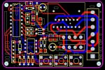
Available was a 1.8 degree, 2.6 Ohm, 4Nm stepper motor and a 2A stepper controller containing a L298n driver and an 18 pin micro, both from ebay.

At the relatively fast stepping rate the current would be within the capability of the L298 but there is no access to the enable pins on this controller so when stationary the current would be excessive. Happily the installed 18 pin micro used pins 17,18,1,2 for the motor and 7,8,9 for switched inputs with pull-ups and this accorded well with the Picaxe 18M2.

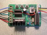
Removing one pull-up made an adc pin available for a potentiometer for the number of steps and one input starts the stepping sequence that ends in outputting 0000 cutting power to the motor. An adaptor was made to allow a sm 7805l to replace the original onboard memory chip eliminating the previous need for a separate 5V supply.

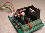
At 1.2 second lift and 3 sec drop the heatsink reaches a steady 40 degrees in an ambient of 20 after 25 minutes running.
This board is an independently functioning stepper motor controller available for very little more than the bare L298 chip price in the UK and a doddle to change to an 18M2.

Dave
 

Attachments

westaust55

Moderator
Good information provided for those seeking to do similar stepper motor Control.

Can I suggest that you:
1. Post your program for future reference by others, and
2. Provide a link and details to the stepper motor controller board, and
3. Post a schematic showing how you hooked it all up
 

WHITEKNUCKLES

New Member
Westaust55,

Thank you.
But the setup, current management and stepping rutine came from your own tutorial on steppers.

http://www.picaxeforum.co.uk/showthread.php?t=14205

However this project is for a one-time electrician who has no knowledge of programming so it is set out to be simple to understand and easily altered by someone willing to use a computer.
The requirement is to draw in material between rollers with a pull of 1 Lb, so a safety factor of 2, well 1Lb 15 & 3/4 ozs used. For contineous testing a cord was wraped arround a rough sawn octagonal drum lifting a selection of kitchen balance weights for the preset distance which then unwinds onto the operating switch. The octagon is ugly and causes oscilations but quick, easy and functional.
http://www.youtube.com/watch?v=T_Vfxuk8x_A

There are a number of sellers of the board, This one has good pictures and many days to go.
http://cgi.ebay.co.uk/Stepper-Motor-Speed-Pulse-Controller-Driver-Board-/330528908729?pt=LH_DefaultDomain_3&hash=item4cf50ee5b9

More information and track layouts here.
http://www.nbglin.com/motor.htm

On the right of my picture in the previous post, the off-board connector when 18M2 installed =.

Black from pin 9, b.3 to Run Switch, 10k pullup third resistor from right above.
Yellow from pin 8, b.2 to 10k Potentiometer wiper having removed the second resistor above.
Green from Ground, system negative return from pot and run switch.
Red from 5v Positive to top of pot via the 78L05 adaptor which required the original 5v protection diode beside the socket to be shorted above the board.

The board can be returned to it's original functional state in a couple of minutes.

The 78L05 is only needed for the long term use intended, AA batteries on red and green work fine.
If a board is too simple to need cad I usually scratch through the photoresist on the corner of a piece of Photoboard using the back edge of a Swan Morton blade in the brass handle, hack it off and dunk it in etchant. I soldered socket/pins from a turned pin I/C socket to the underside, 2 scores on the top plus 2 vias to the power pins.

If the potentiometer is set to maximum at switch-on, there is a 7 second delay to allow the pot to be set to a new stepping number otherwise the previously recording is used. Simplistic accelleration is used for more grunt at start-up.

Dave

Code:
'Picaxe 18M2
'If pot < max then recording to be used
'else wait 7sec; record adin and continue
'lift 2Lbs 1/5inch to 12inch/sec;3"drum
'All after(')comment & ignored by Picaxe

#Picaxe 18M2
symbol stepcount = b4 '...counter variable
symbol adin = b2 '........number of steps
symbol swin = pinB.3 '....activation switch
output c.0 '..............}define pins
output c.1 '..............}as outputs
output c.2 '..............}c.3 always output

 pinsc = %00000000 '......no power to motor
 readadc b.2,adin '.......potentiometer
if adin <254 then start '.change adin?
 pause 7000 '.............position pot;in 7
 readadc b.2,adin '.......read in new adin
 adin = adin / 4 '........4steps=1/5inch
write 0,adin '............save to memory

start: 
 if swin = 1 then delay1 'await active low
delay1: '.................}debounce switch
 pause 10 '...............}settiling time
 if swin = 1 then start '.}

 stepcount = 0 '..........restart counter
 read 0,adin '............read from memory
 pinsc = %00001010 '......steping sequence
 pause 6 '................slow stepping
 pinsc = %00001001
 pause 6
 pinsc = %00000101
 pause 6
 pinsc = %00000110
 pause 6
 inc stepcount
if stepcount => adin then prevent

 pinsc = %00001010
 pause 6
 pinsc = %00001001
 pause 6
 pinsc = %00000101
 pause 6
 pinsc = %00000110
 pause 6
 inc stepcount
if stepcount => adin then prevent

 pinsc = %00001010
 pause 5 '................increase speed
 pinsc = %00001001
 pause 5
 pinsc = %00000101
 pause 5
 pinsc = %00000110
 pause 5
 inc stepcount
if stepcount => adin then prevent

many:
 pinsc = %00001010
 pause 4 '................final speed
 pinsc = %00001001
 pause 4
 pinsc = %00000101
 pause 4
 pinsc = %00000110
 pause 4
 inc stepcount
if stepcount < adin then many'comlete sequence

prevent: '................prevent shoot through
 pinsc = %00000000 '......no power to motor
 if swin = 0 then delay2 'debounce
delay2:  
 pause 10
 if swin = 0 then prevent
 goto start
 
Last edited:

WHITEKNUCKLES

New Member
Rbeckett,

The nearest thing that I could find to a schematic was the board layout below.

As received the board has a Microchip CF745 18 pin microcontroller where pins 17,18,1,2 lead to the output connector for the stepper motor on the right of the diagram.
Pins 6,7,8,9 have 10k pull-up resistors and lead to the input connector on the lower left.
Replacing this chip with a Picaxe 18M2 puts the stepper on pins C.0 to C.3 and the inputs on pins B.0 to B.3.

I used B.3 for the microswitch that starts the stepping sequence and removed one pull-up resistor for a potentiometer on an adc on B.2 for the number of steps.
The web links posted previously have good photos and setups but if you have any questions on wiring the parts together I would help in any way I can.

Dave.
 

Attachments

WHITEKNUCKLES

New Member
Further Hacking

This project started with a stand alone stepper controller with microstepping and current selection together with an industrial power unit. A picaxe 08M prototype board with a switch, a pot and a battery pulsed the controller for every step and worked over hours of soak testing. "Sturdy but could it be made smaller?"

On this board the + 5v track to pin 9 of the L298 takes a dogleg past pin 6 and extends to pin11 the enable pins and they are easily isolated and after removing a resistor, connected back above board to pin B.6 one of the PWM pins on the 18M2.

The datasheet recommends:
Quote
"...control the current amplitude by chopping the inputs...provide overcurrent protection by switching low the enable."

The datasheet is at odds with the Appnotes further down which disagree with each other.
So 8kH at 80% allowed the voltage dropping resistors to be removed accompanied by a reduction of 30% in the current.

Dave

http://datasheet.octopart.com/L298N-STMicroelectronics-datasheet-56587.pdf

ST Apnote monolithic bridge drivers
http://www.oricomtech.com/download/st-an298.pdf

AN460 chop mode benefits
http://www.st.com/stonline/books/pdf/docs/1675.pdf
 

Attachments

WHITEKNUCKLES

New Member
Directly replacing a pull-up resistor on pin 13 with a 10k preset (one leg to ground plane) allows the adc on B.7 to regulate the pwm on B.6 to between 50% and 100%.

An estimated 80% of the preset travel lifts 2 lb at 0.42A and 60% travel lifts 12 oz at 0.23A.

A separately encased 10v-0-10v 2A transformer, two 3A diodes and a 4700uf 40v (5A ripple) electrolytic provide power.

Dave
 

Attachments

Top