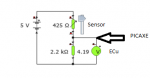
I'm trying to measure a thermistor coolant sensor, which is fed from a 5V line (with a 2k pulldown in the ECU) with a PICAXE 40X2
I don't want to disturb the voltage reading of the sensor that the ECU sees (which varies from 145ohms to 2.45k, hence 2.247V-4.662V).
I presume I need to scale that 0-5V to 0-3.3V for adc10 but a divider would change the pulldown resistance for the ECU, disturbing the ECU's divider?
Any ideas?
Thanks!
James
")