readadc or readadc10

davidwf

Senior Member
Would someone kindly advise me IN SIMPLE TERMS the difference between readadc and readadc10....I understand that it returns 8 or 10 bits but when / why would you use each ?

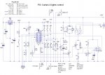
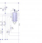
For an external light controller I am trying to read the light level using an LDR connected to pin 1 of a PICAXE 18X (I need extra in / out so the 18X is required) and 0 to 255 is not giving me enough range - the required levels are around 10 to 20.

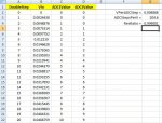
Am I wrong in assuming that readadc10 would give me a greater range ?

I am using a PICAXE 18X

Thanks

main:

SYMBOL dark_level = 10
SYMBOL light_level = 20

check: readadc 2,b0 ' ADC input 2 - dark sensor,PIC pin 1, read into b0
if b0=<dark_level then dark ' condition if dark
if b0>=light_level then light ' condition if light
 

Attachments

Last edited:

Jeremy Leach

Senior Member
Hi, the difference in bits is the resolution. The voltage range measured by the picaxe ADC is the same for both commands. So with ReadAC10 you get 4 times the numbers of levels. It's a bit like going between two floors in a building but going up two different staircases, one with 255 steps, the other with 1023. The height difference between the floors is still the same.

So for your purposes your picaxe will be more sensitive to light changes if it uses readADC10 - it will be able to detect the boundary between 'light' and 'dark' more finely.

Sometimes you just don't need the resolution of readadc10 and because you need to put the result of readadc10 into a word variable whereas readadc uses a byte variable, it is more convenient to stick to readadc. Having said that I personally almost always use readadc10 !

Hope this helps
 
Last edited:

davidwf

Senior Member
Jeremy
Thanks for your prompt reply....do I need to use any additional coding for readadc10 or just amend the trigger value ?

Thanks
 

Jeremy Leach

Senior Member
Hi, you'll need to ammed the trigger value (multiply by 4 and then tweak as you need to), plus remember to read into a word variable (w0,w1 etc).
 

davidwf

Senior Member
I realised about x by 4 but forgot about w0 rather than b0....dammit, no wonder I was getting stupid results !

Works OK now - 0 to 1000 ish

Thanks again
Dave F
 

Grant Fleming

Senior Member
Hi, the difference in bits is the resolution. The voltage range measured by the picaxe ADC is the same for both commands. So with ReadAC10 you get 4 times the numbers of levels. It's a bit like going between two floors in a building but going up two different staircases, one with 255 steps, the other with 1023. The height difference between the floors is still the same.
Jeremy,
I do like that analogy, easy to picture!
 

Michael 2727

Senior Member
Also renember-
At resolutions of 10 bit and higher, ADC power-supply/reference-voltage stability
can become an issue for very fine readings.
E.g. 10 bit, 5V divided by 1024 steps = 0.0048V per-step.
 

BeanieBots

Moderator
You might also want to consider changing the value of R4.
If you are only getting small numbers, it suggests that the resistance of the LDR at the light levels you are interested in is too high. Try increasing the value of R4 from 10k to 22k.
 

Jeremy Leach

Senior Member
I wonder if there is a way of doubling the resolution by pairing up two picaxe ADCs somehow? Probably a crazy idea and I know that there are all sorts of issues with high res.

It would be interesting to just see if you get the same reading from two ADCs on the same picaxe ...I've never tried.
 
Last edited:

Dippy

Moderator
"I wonder if there is a way of doubling the resolution by pairing up two picaxe ADCs somehow? Probably a crazy idea and I know that there are all sorts of issues with high res."

- no. You haven't any control over PIC ADC once a conversion starts.

Just buy (sorry) an external ADC and then suffer the problems of high res ADCery.
 

Jeremy Leach

Senior Member
I was thinking more about offsetting the input voltage by a 'half-step' amount on one input somehow. Anyway ... pretty sure it's not a practical suggestion because it's such a small amount, but here's an idea you can shoot down ...

Code:
                          .------.
 VIn                      |      |
   o----o----o------------oADC1  |
        |    |            |      |
        |   .-.           |      |
        '   | |R1     '---oADC2  |
        |   | |       |   |      |
     D1 V   '-'       |   '------'
        -    |        |
        |    o--------'
        .    |
        |   .-.
        |   | |
        |   | |R2
        |   '-'
        |    |
        '----.
            .'.
            | |
            | |R3
            '-'
             |
             |
  -----------o-----------------------
The voltage drop across the diode is constant (ok, cue comments..)
R1 and R2 are selected so that the voltage drop across R1 is a half-step voltage. (if 5V supply and 1023 steps, half-step = 0.0024V)
You read in both ADC values and have double the resolution of just using one ADC.
 
Last edited:

Jeremy Leach

Senior Member
Actually, have worked out that IN THEORY you don't need a diode at all if you are measuring only a small range. For instance:

Code:
                          .-------------.
                          |             |
                          |             |
                          |             |
                          |  ADC1       |
   Vin o----------o-------o             |
                 .-.      |             |
                 | |      |             |
              R1 | |      |             |
                 '-'      |             |
                  o-------o             |
                  |       |  ADC2       |
                 .-.      |             |
              R2 | |      |             |
                 | |      '-------------'
                 '-'
      o-----------o------------o
.
.
.
If R1/R2 = 1/1000 then it turns out, doing the maths, that in the range of ADC1 0 to 500:

If ADC1 reading <> ADC2 reading then it's a whole step
If ADC1 reading = ADC2 reading then it's a half step

So it's easy to get double resolution by:
Code:
DoubleRes = ADC1*2
If ADC1 = ADC2 Then
    Inc DoubleRes
Endif
 
Last edited:

Dippy

Moderator
Eh, don't follow.
With a ratio of 1/1000 you're probably exceeding the practical precision of the ADC.
I don't see how it can give you better than 10bit?
Even on a good day surely that is simply correcting 1 bit isn't it?
Vsupply would have to be very stable.
On PICs when doing greater than 10bit you use a precision reference selectable in an SFR and cover the whole thing in capacitors.

I think we may have seen a Microchip App Note if this was practical ;)
 

BeanieBots

Moderator
Just about the only way to get better than the hardware accuracy of any given ADC is to inject noise and take an average. YES, that's right, inject NOISE. (Ideally, white noise).
If the hardware itself was cabable of giving better resolution/accuracy, it would do so and not be limited. Otherwise it has been overengineered and that quite simply is not done at chip level.
As pointed out by Dippy, you also need to consider the reference voltage. In fact, you will probably find that without good decoupling, the PICAXE puts enough noise on the power rail to do the job.
Try it!
 

Jeremy Leach

Senior Member
Guys, I don't doubt the issues, but from a theoretical point of view the maths shows it works, seriously. I'm not going to try it because I haven't got a reason to, and I know there will be all the issues with power supply etc :)

The key thing with my idea is that it uses two ADCs, and this is how together they can exceed the resolution of a single ADC. If I could upload a spreadsheet I could show you.
 
Last edited:

premelec

Senior Member
Hi Jeremy, I think perhaps you are not noting that the ADC value's reference is the PICAXE power supply so what's done at the ADC pin doesn't change basic resolution... however if
you could switch the power supply between two values, say 5 and 3 volts, the then step bit value changes. I don't know if you can do this without messing up the PICAXE's running but expect you could if you didn't change the power supply too fast [= >20msec?]. As pointed out ditering is used sometimes to get an extra bit...

Often times an external scaling amplifier or ADC makes more practical sense... have fun!
 

Jeremy Leach

Senior Member
Well, I'm just purely going by maths and don't get me wrong, I respect your knowledge of what works in practice. Just to try to explain the maths, I've uploaded a little pic of the spreadsheet, and here's an attempt at a description ...

DoubleStep column is numbers 0 to 2046 (2 * 1023)
CellB2 has formula '=A2*VPerADCStep * 0.5'
CellC2 has formula '=INT(B2*ADCStepsPerV)'
CellD2 has formula '=INT(B2*StepsPerV*ResRatio)'

VPerADCStep is a named cell at G2 with formula '=5/1023'
ADCStepsPerV is a named call at G3 with formula '=1023/5'
ResRatio is a named cell at G4 with formula '=1000/(1000 + 1)'

The column formulae are copied down.

Looking at the ADCValue columns, you can see (apart from 0 ADC values) that when the ADC values are equal the doublestep value is odd , and when they are different the double step value is even. This pattern repeats up until an ADC Value of 500. So by comparing the ADC values (using the simple code already mentioned) you can get double resolution.
 

Attachments

BeanieBots

Moderator
Jeremy, I don't want to put you off further analysis, but your "maths" has not taken into account everything that is involved. That is why it does not show that the "theory" doesn't work.
For a simple example, try taking it a little further. Such as this theory.
I emphasise that this WILL NOT WORK but try the (simplified) maths!.

PWMout has a 10-bit resolution.
ReadADC10 has a 10-bit resolution.
Convert the PWM into an analogue voltage and add it to the unknown voltage.
Take an ADC reading.
Slowly increase the PWM until the ADC changes by 1.
You now know (to 10-bit resolution) how far short of the next ADC count your unknown voltage was. Hence you can read the voltage to 1023 BETWEEN each of the ADC steps. The maths shows it works!
That's a 20-bit ADC!

For a mechanical analogy, it would be the same as taking a 1m rule with a micrometer glued to the end and claiming that you can now measure 1m to within 0.01mm. The bit youv'e missed is that the 1m rule is only good for +/-1mm due to how hard you pull it, the local weather conditions and many other factors which were not included in the maths.
 

moxhamj

New Member
As premelec says, you can get higher resolution if you want to only work over a smaller range. You can use an op amp to (say) multiply by 3, move the offset so it sits in the middle of the range you are interested in, and accept that the output may end up clamped at 0V or 5V. But you will need a very stable referrence on the op amp and a very stable power supply, and I very much doubt you will get much better than 10 bit anyway.

I tend to do most of my work at 8 bits and so 10 bits are a bonus. If you look at it that way, 11 bits almost seems a bit greedy!
 
Last edited:

Jeremy Leach

Senior Member
I totally agree that 'other factors' will make the whole thing unworkable BB. I was just looking at it from theory, assuming those other factors didn't exist :)

It just interested me how it could even work in theory, and how two (or more) of the same device can give better results than just one - I'm sure there's a technical word for this principle but not sure !

I like that PWM idea ...but don't worry, I'm not going to try it ;)
 
Last edited:

BeanieBots

Moderator
Jeremy, you should try it.
If you're careful and do it with quality components, you might actually get 11 or maybe even 12 bit results!
More's the point. Do the maths. I mean ALL the maths. Then you will see how things like the PICAXE clock, power supply and temperature to name just a few, will effect your results.
There's no end to how far you can take the maths. Believe it or not, you'll find that the decoupling caps (you do fit them don't you) can have one of the most significant effects on ADC readings.

Take the leap. Move from ideal to real. You already have an interest and a mathematical ability. Go for it. It can actually be quite rewarding. Op-amps is a good place to start. I'm sure you are familiar with the basic maths for calculating gains etc. Now add into those equations things such as input offset, input bias current, gain and output impedance.
After that, you will then have a "feel" for what can and cannot be ignored and under what conditions. If you don't, you'll fall into the trap that many good engineers fall into. "It worked in the simulator!".
 

Dippy

Moderator
Well, I like fiddling with maths too and it's an interesting exercise for the grey matter -especially proving 1=0. And then moving on to "Oh",said God...etc.

I guess taking this further with several ADCs you could (theoretically) do the ADC equivalent of those old fashioned vernier scales on micrometers. It doesn't provide any more length but gives more precision (maybe, I haven't checked your maths) on paper. Anyway, it briefly jiggled the old cerebellum on a Sunday.

BB:
"If you don't, you'll fall into the trap that many good engineers fall into. "It worked in the simulator!"."
- gosh, I've seen that a few times and not just on this Forum.
Along with: "I haven't tried this myself, but..." and "will this code/circuit work?"
- why are people so reluctant to try things? (I'm not on about J here btw).
 
Last edited:

BeanieBots

Moderator
Thanks, Dippy. Vernier was the word I was looking for. Good analogy.
It CAN be made to work, but only with a FULL understanding.
 

Jeremy Leach

Senior Member
"why are people so reluctant to try things?"
After chewing over the theory, deliberating, and having friendly banter here, there often isn't much time left to actually do anything ;)
 

Dippy

Moderator
Blimey J. Not enough time?

Yesterday, I managed to code a spectrum analyser display, feed the cat and insult at least half a dozen people on this Forum! It's all about time management.
Don't talk... eat! (An old TV ad for cream cakes that stuck in my head.)
 

BeanieBots

Moderator
Sorry Jez, I have to agree with Dippy about the time thing.
When it comes to simulators, more often than not it's actually quicker to "do".
Get yourself an AXE090. Takes nearly all PICAXEs, has a small proto area.
Takes seconds to "try" most things.
Once you've "done" a few more things, you'll also have a better idea of what is / is not worth "doing". (and why).
 

davidwf

Senior Member
Ongoing from my original request I am heving problems sensing light / dark and vice versa....

I have attached the complete project - also listed elsewhere on the forum as my curtain & lights controller.
Although it works "on the bench" and switches OK when the sensor is shielded or exposed to light, when installed it refuses to switch either way - i.e. with the light level changing slowly.

I have de-bugged the sensor reading back to the PC and it is being read OK

Any ideas appreciated
Thanks
 

Attachments

Dippy

Moderator
I haven't got time to chek your prog but have you tried inserting some debug/sertxd statements at the appropriate plces in your code when installed to see what is happening?
e.g. sertxd(“Entering Light routine LDR ADC= ”,#w0,13,10)
 

BeanieBots

Moderator
Was about to say what Dippy's just said but he beat me to it.
Your circuit looks OK but I don't have the time either to go through your code.
One thing to rule out, does it behave the same with/without programming cable attached?
In addition to adding some debug statements, have you tried a VERY simple prog that does nothing more than test the LDR and maybe set an LED on/off? That would eliminate hardware issues and let you concentrate on code issues.
Build it up the code one section at a time. Don't move on until 100% confident that each section does exactly as you intended it to.

What's different between bench and "real" location?
Light levels? Programming Cable? Length of wire to LDR? Power supply? Proximity to TV?

Also, did you try changing the value of R4 as suggested earlier?
 
Last edited:

davidwf

Senior Member
You might also want to consider changing the value of R4.
If you are only getting small numbers, it suggests that the resistance of the LDR at the light levels you are interested in is too high. Try increasing the value of R4 from 10k to 22k.
Thanks, the LDR resistance is nearer 1Meg at the light levels concerned so I have upped R4 to 470K which should give a more usable range......might even go higher, we shall see
 

Dippy

Moderator
Be aware of ADC and 'source' impedances/resistances. Things can go a bit funny at high values. PIC data sheets suggest no higher than 10K, though I think that value is a little conservative.. but 1MOhm and 470K mmm.

When I did a circuit ages ago sensing low light levels I found a capacitor at that point helped a bit. But as that was a bodge I ended up using a TAOS light-voltage sensor which was which better. I can't remember device id.
 

BeanieBots

Moderator
Hmm....
If your LDR is close to 1M, then you certainly need to increase R4, BUT, there is a maximum source impedance for analogue inputs of around 20K.
(the actual spec in the DATASHEET is 10k).
1M//470K = 320K which is way over spec.

In practice, you might be able to get around this by adding 100nF on the ADC pin. As an absolute minimum, you will need to employ the enhanced download circuit or your readings will be significantly different with/without the download cable fitted.

Try the 100nF cap first. If it's too erratic/unstable/inconsistant, then you will have to consider an op-amp buffer. Also, make sure the leads between LDR and PICAXE are as short as possible. An "aerial" on a 320K load will pick up a lot of mains interferance (hum) let alone anything else.

EDIT: Dippy slipped in first again!
 

davidwf

Senior Member
The need to use an op-amp buffer is a bit dissapointing although I can see your thinking......surely it doesn't MATTER what the actual input level is (with a 10K resistor connected) ...as the trigger point can be altered in software.

....which brings me back to the original query as to why it won't switch under "normal" conditions - i.e. slowly changing values - but it is OK on the bench going from light to dark etc.

Thanks
 

BeanieBots

Moderator
You're correct in so far as it shouldn't matter what the level is. However, there is doubt regarding what those levels actually are. Hence all the suggested tests to determine what is actually going on.
Of course, it could just be your code.

I'd still suggest taking R4 up to about 47K and 100nF on ADC pin.
 

Dippy

Moderator
With risk of pedantifisation:

Lets go back to your LDR and proposed 470K.

The ADC works by charging up a weeny on-board capacitor, disconnecting the input and then discharging it in discrete steps until it has reached a low V reference. It does this very rapidly and remember a PIC has an onboard comparator. Some PICs use a slightly different method but the sampling cap is common.
The charging-up time is controlled by firmware and is very brief. So from schoolboy capacitor theory you can see that if the source resistance is very high then the weeny cap won't have fully charged in the brief time. If the source res was zero (on the other hand) then charging is 'instant'.

This has two unwanted effects;
1. With an LDR at 1Mohm it is unlikely that the sample (weeny) cap has fully chraged in the time. It is a little more complicated than that in reality.
2. Fast repetitive ADCing with a high source may even give the (numeric) impression that the level is going down.

With a lower input res then the cap charging is very quick and all is happy.

As to your question; why OK on bench but not when slow? I don't know. I could theorise but won't. It may be that , on bench, the sudden light-on allows enough to make the ADC work properly. But a gradual dark to not-so-dark still doesn't allow the sample cap to charge up between discharges. But if thats the case then it should show up as 'light' whn a bright light came along. Oh, I don't know.
But, whatever, the bottom line is that your light sensing ciruit as it stands is not ideal and should really be modified. Try a 100nF cap in there and see if it makes a diff.

I'll find out what sensor I used. I had a similar problem by the way and it showed up as inconsistent ADC values when I ADC'd repetitively.
 
Last edited:

davidwf

Senior Member
You're correct in so far as it shouldn't matter what the level is. However, there is doubt regarding what those levels actually are. Hence all the suggested tests to determine what is actually going on.
Of course, it could just be your code.

I'd still suggest taking R4 up to about 47K and 100nF on ADC pin.
OK, will do.....as a point of interest, if I power up the cct (or reset it) at night - i.e. with the sensor "dark", after the requisite 20 min delay it operates OK, likewise if I reset with the sensor under "light" conditions the correct output is applied after 20 mins, so clearly the PIC is reading it Ok and the program is OK......
 

BeanieBots

Moderator
if I power up the cct (or reset it) at night - i.e. with the sensor "dark", after the requisite 20 min delay it operates OK, likewise if I reset with the sensor under "light" conditions the correct output is applied after 20 mins, so clearly the PIC is reading it Ok and the program is OK......
On the contrary. I'd say that suggests hardware working OK and a software error! I'll try to spend some time looking at your code but probably not soon.
 

davidwf

Senior Member
..........

you will need to employ the enhanced download circuit or your readings will be significantly different with/without the download cable fitted.

EDIT: Dippy slipped in first again!
..... remind me if you will where this lives...I have seen it but cannot find it !

Thanks
 
Top