Jeremy Leach
Senior Member
I'm working on a little maths utility that 'might' be able to help with PID - not sure yet...
")
		#PICAXE28X2
pause 1000
high B.5
high B.4
pause 1000

		hi2csetup i2cmaster,%00110011,i2cslow,i2cbyte


main:		'hi2cout 0,(0x80)
		'hi2cin %00000011,(b2)
		'hi2cin %00000010,(b3)
		'hi2cout %00110010,(%00110011)
		'hi2cin (b2)
		hi2cin 3,(b2)
		hi2cin 2,(b3)
		'hi2cin %10000010,(b1)
		'hi2cin %10000100,(b2)
		let bit0 = bit20
		let bit1 = bit21
		let bit2 = bit22
		let bit3 = bit23
		let bit4 = bit24
		let bit5 = bit25
		let bit6 = bit26
		let bit7 = bit27
		let bit8 = bit28
		let bit9 = bit29
		let bit10 = bit30
		let bit11 = bit31
		sertxd (#w0,",")
		'sertxd (#b1,",")
		'sertxd (#b2,",")
		'debug
goto mainhi2csetup i2cmaster,%00011011,i2cslow,i2cbytehi2csetup i2cmaster,%0001101,i2cslow,i2cbyte
(without the last digit of the slave address)
		#PICAXE28X2
pause 1000
high B.5
high B.4
pause 1000

		hi2csetup i2cmaster,%00011001,i2cslow,i2cbyte


main:		'hi2cout 0,(0x80)
		'hi2cin %00000011,(b2)
		'hi2cin %00000010,(b3)
		'hi2cout %00110010,(%00110011)
		'hi2cin (b2)
		hi2cin 3,(b2)
		hi2cin 2,(b3)
		'hi2cin %10000010,(b1)
		'hi2cin %10000100,(b2)
		let bit0 = bit20
		let bit1 = bit21
		let bit2 = bit22
		let bit3 = bit23
		let bit4 = bit24
		let bit5 = bit25
		let bit6 = bit26
		let bit7 = bit27
		let bit8 = bit28
		let bit9 = bit29
		let bit10 = bit30
		let bit11 = bit31
		sertxd (#w0,",")
		'sertxd (#b1,",")
		'sertxd (#b2,",")
		'debug
		goto main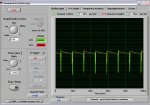
 . This is a slight issue.. I haven't tried using the normal commands and will do that now (without scope). I have tried an EEPROM chip with no success. It is a ST microelectronics version of the 24LCxx series from microchip so it is very similar to the one in the I2C example, but I de-soldered it from a TV so it could be fried.
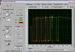
No idea if this will work but its worth a shot.I'll see if I can find some faster software, but the 44100 might be the limmit of the hardware.
		#PICAXE28X2
pause 1000
high B.5
high B.4
pause 1000
setfreq m1

		i2cslave %1010000,255,i2cword

main:		writei2c 1,(13)
		pause 50
		readi2c 1,(b0)
		sertxd (#b0,",")
		goto main
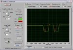
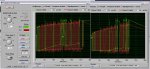
...that is cool.Bingo ! That does look like an I2C header ...
Start bit (S), SDA goes low followed by SCL going low
7 x I2C address bits, SCL pulses high
Write/Read bit (W=0/R=1), SCL pulses high
Ack/Nak bit (A=0/N=1), SCL pulses high
Stop bit (P), SDA goes high followed by SCL going high
So, that's "S0101000WNP", and that's a NAK because the 7-bit I2C address is 0101000 when it should be 1010000 for Eeprom.
Change to "I2cSlave %10100000,255,i2cword" and you should get "S1010000WA..."
		#PICAXE28X2
pause 1000
high B.5
high B.4
pause 1000
setfreq m1

		i2cslave %10100000,255,i2cword
		let b1 = 0

main:		inc b1
		writei2c 1,(b1)
		pause 50
		readi2c 1,(b0)
		sertxd (#b0,",",#b1,",")
		goto main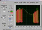
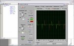
Master:                        S0011001W 00000011 S0011001R         NAP
Slave: A A AXXXXXXXXMaster: S0011001W ??P
Slave: A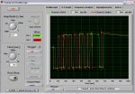
		#PICAXE28X2
pause 1000
high B.5
high B.4
pause 1000
setfreq m1

		i2cslave %00110010,255,i2cbyte

		let b1 = 0
		SERTXD("RESET")
main:		pause 50
		readi2c 3,(b0)
		sertxd (#b0,",")
		goto main