RC Car lights

Andrew Cowan

Senior Member
Hi!

I have completed building the lighting circuit for my rc car.

I responds to steering and throttle controls with lights (indicators and reversing/braking lights). However, I want to also make it so that when the transmitter is turned off, all the lights flash.

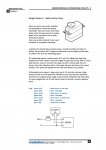
Note I have put a connector in the PCB - this connects the lights (all over the car on wires
), to the PCB.

There is, however a slight problem.

When the connector is disconnected, so the lights and wires are not connected to the car, there is no problem when the radio is turned off. The signal is at 0 (measured with pulsin). The servos in the car do not move.

This is what I expected.

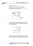
When the connector is connected, there is a change. There is a huge amount of interference, the servos go crazy, and there is not a fixed pulsin signal.

I cannot understand this, as the reciever is only connected to the PIC board via 0V and signal. Why is it that the lighting part of the circuit is making interference?

Once the transmitter is turned on again, all interference goes, and the car works normally.

Andrew. Any ideas?

PS - apart from this interference, the circuit works perfectly.
 

Attachments

Last edited:

gbrusseau

Senior Member
I'm going to make two assumptions first. The servos are connected to the 18X rather then the radio. The radio is connected to the 18X. Usually the servos are part of the radio.

There's a real good chance your over driving the 18X LEDs output pins. With no current limiting resistors in series with the LEDs, this could be the case, depending on the spec of the transistors and LEDs. If the 18X output pins are being over-driven, that could cause the floating radio input pin of the 18X (Radio Off) to see ground noise.

Try current limiting resistors for the LEDs circuit (transistor collector output). This resistor could be somewhere between 100 ohms and 300 ohms I think. Use a 10K pull-down resistor on the radio input. Place current limiting 330 ohm resistors between the 18X LED* output pins and the base of your transistors.
 
Last edited:

Mycroft2152

Senior Member
With some high intensity LEDs that use only a few milliamps, like those from Xmas tree light strngs, you will not need the transistors, but can drive the LEDs directly from the PICAXE.

In any event you will need current limiting resitors for the LEDS (330 - 1000 ohms).

Myc
 
Last edited:

Andrew Cowan

Senior Member
Sorry - I was being lazy while drawing that schematic. The LEDs are very powerful ones, drawing about 40ma each, so they do need the transistors. I do have resistors in place, they are just not drawn.

Also, the signal does not pass through the PIC - a Y cable is used to connect both the servo and the PIC board to the reciever.

Andrew.

Thanks for your help!
 

Dippy

Moderator
What is your power supply exactly?

Could it be that all those LEDs switching cause a little power dip and upset the PICAXE?
Have you tried putting a capacitor or two right next to PICAXE +Vsupply pin?
Sometimes a capacitor here will prevent litte power glitches upsetting things.
It should be 'standard practice' I always suggest.

Or is there anything else that you haven't included in your posted schematic? (Sorry, I don't mean to sound too sarcy but if you leave things out then you just waste time with q&As)
 

Andrew Cowan

Senior Member
You spelled scary wong :)

That other schematic (now updated) was meant to be a block diagram, showing what was going on.

Here is the full one. I'm welcome to all ideas and criticism. About a possible power dip - it is not the PICAXE that is being upset, it is the reciever (that has a seperate power supply).

Andrew
 

Attachments

Last edited:

eclectic

Moderator
Andrew.
Like your Uncle Dippy, I'll try not to be sarky / sarcastic.

But, on your FULL circuit, have you tied down the unused inputs?

And why do you need transistors and 40mA for the LED's?
Are you sending the car down the M1?
Use 2k resistors.

e.
 

Wrenow

Senior Member
Ahem, in correting spelling, good to be careful in one's own ("poser supply") ;-)

Personally, I would try tying the signal input and all other input pins low. Just a guess from something rattling around in the back of my mind I can't quite put a finger on, though.

Cheers,

Wreno
 

goom

Senior Member
With the receiver connected, but turned off, the steering servo and speed controller will get whatever stray signals that are being picked up by the signal wires. The flashing LED's could well result in "random" signals getting into the signal circuit. You could confirm by reprogramming the PICAXE (temporarily) to turn the lights permanently on or off (no flashing).
Some possible solutions:
Tie the signal wires to ground via a resistor (10K?). Can't do any damage, and worth a try.
Instead of the "Y" connection, read the 2 signals with "pulsin" and output to the servos with "pulsout". Trap for invalid signals (e.g. <90 or >210), and output a default on the pulsout pins (e.g 150) if the input is out of range. This should keep the servo/ESC steady and at a preferred failsafe value.

By the way, I think that it is "spelled" not "spelt".

Let us know how things go.
 

Andrew Cowan

Senior Member
Thanks for the reply.

Things to try:
Tie the signal to ground (10K)
Improve my spelling
Try the circuit with no flashing LEDs
Try the circuit with no LEDs on (to determine if the problem is with the wiring ot LEDs)
Add resistors to the servos and transistors.

Thanks again goom!

Andrew
 

Wrenow

Senior Member
Actually, try tying all input pins (not just those receiving signals) to ground.

Just a thought.

Wreno
 

jodicalhon

New Member
By the way, I think that it is "spelled" not "spelt".
Either is fine. Depends which school you went to.

(Hmmm, I ended that last sentence with a preposition...err..."depends on the school to which you went"?...err..."depends on the school you attended"?...err..."depends on the school from which you were expelled"? Yes, I think that's right.)
 
Top