Andrei IRL
Senior Member
I have completed a project and i am having an issue.
Some times, for no good reason the Circuits gets triggered by itself.
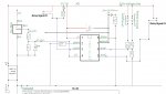
Basicaly, i have an input from PNP Induction proximity sensor connected to C.3. Proximity sensor outputs 12V so im using voltage divider to bring it down to 4 volts and also have use Zenner diode 4V7 to make sure that PICAXE will never get more then 4.7 volts in case of spike of voltage (this is to be fitted in a vehicle). When proximity sensor meets metal object PICAXE triggers relay module (it has build in resistors, transistors and EMF diodes thats why they are not showing on the schematics)..
All is working rather well, accept for some times the relay gets triggered by itself.
I have re checked everything and tried to replicate the issue but not sure what exactly causes it to happen.
I have attached schematics and CODE in case some one would have a minute to go over them nad possibly point me in the right direction.
Thanks very much in advance.
Andrei.
Some times, for no good reason the Circuits gets triggered by itself.
Basicaly, i have an input from PNP Induction proximity sensor connected to C.3. Proximity sensor outputs 12V so im using voltage divider to bring it down to 4 volts and also have use Zenner diode 4V7 to make sure that PICAXE will never get more then 4.7 volts in case of spike of voltage (this is to be fitted in a vehicle). When proximity sensor meets metal object PICAXE triggers relay module (it has build in resistors, transistors and EMF diodes thats why they are not showing on the schematics)..
All is working rather well, accept for some times the relay gets triggered by itself.
I have re checked everything and tried to replicate the issue but not sure what exactly causes it to happen.
I have attached schematics and CODE in case some one would have a minute to go over them nad possibly point me in the right direction.
Thanks very much in advance.
Andrei.
Code:
setfreq m8 ` Running at 8Mhz, all pause values are x2 times
symbol qs=pin3
symbol up=pin1
symbol down=pin2
symbol greenled=0 	`ready LED
symbol RELAY1=4
symbol RELAY2=2
symbol kill = b0
symbol patern=b1
read 0,kill
read 1,patern
ReadAdc 1, b2
	Select Case b2
  		Case > 106 : Goto raceshift
  		Case > 42  : Goto roadshift
  		Else       : goto main
	End Select

Raceshift: patern = 0	`race shift - pull
	For b3=0 to 4	`RED and GREEN LEDs flashing 5 times on power ON
	high greenled
	high relay1
	pause 600		`300ms
	low greenled
	low relay1
	pause 600		`300ms
	next b3
	write 1,patern
goto main

Roadshift: patern = 1	`road shift - push
	For b4=0 to 4	`RED and GREEN LEDs flashing 5 times on power ON
	high greenled
	high relay1
	pause 600		`300ms
	low greenled
	low relay1
	pause 600		`300ms
	next b4
	write 1,patern
goto main

main:       high greenled
		if qs=patern then fire

	ReadAdc 1, b5
	Select Case b5
  		Case > 144 : Goto BothPushed
  		Case > 106 : Goto Plusone
  		Case > 42  : Goto Minusone
  	End Select


goto main

fire:	     	high relay1
	     	high relay2
		low greenled
		pause kill
		low relay1
		pause 40	`20ms delay between two realys kicking spark back in
		low relay2

		pause 600		 `pause 300ms anti-bounce

waitforquickshifter:if qs=patern then waitforquickshifter

goto main

bothpushed:	kill = 130	`kill time 65ms
		write 0,kill
		low greenled
		For b6=0 to 4
		high greenled
		pause 600 	` pause 300ms
		low greenled
		pause 600	`pause 300ms
	next b6

goto main

plusone:if kill>200 then main		`MAX 100ms
		kill = kill + 2  		`+1ms
		write 0,kill
		low greenled
		pause 1000			`pause 500ms
		high greenled

goto main

minusone:if kill<80 then main		`MIN 40ms
		kill = kill - 2		`-1ms
		write 0,kill
		low greenled
		pause 1000 			`pause 500ms
		high greenled

goto main
Last edited:
")