puddlehaven
Member
For my birthday this year my wife got me a Spare Time Gizmos ELF 2000 kit, a re-interpretation of the original 1802-based computer that I (and many others) built from plans in Popular Electronics.
Just like the first one that I built, this one had a few problems when I first turned it on. Finding and fixing a bad connection in an IDC socket was fairly easy, and I found the cold solder joint on the switch panel after just a little more work. What was harder was the fact that some memory locations just didn't seem to be changing, and I couldn't figure out why.
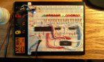
So I built a test rig for the 32K static RAM on the ELF2K. I used a Picaxe 40X1 as the brains, two 74HC595 chips to latch the 15-bit address required, and a handful of LEDs to show me what's going on.
I used PortC to read and write data to the RAM chip. I had some difficulty getting the bi-directional data bus to work until I put "dirs=" statements in the code to explicitly change from output to input when writing then reading the test data.
Since PortC was in use, I couldn't use the hardware SPI port, so I used the simple bit-banged serial protocol from the manual.
Once I had the test rig up and running it started indicating memory errors throughout the RAM chip, but especially on the last page of memory, the page that the ELF2K uses for it's system data page, and where the OS on the ELF2K was indicating there was a problem.
I've ordered a couple more RAM chips that should be here tomorrow. Once I've got a known good RAM chip to install in the ELF2K I'll be one step closer to getting it to work.
I've attached a picture of the test rig on my breadboard, and the code for the test harness follows.
Just like the first one that I built, this one had a few problems when I first turned it on. Finding and fixing a bad connection in an IDC socket was fairly easy, and I found the cold solder joint on the switch panel after just a little more work. What was harder was the fact that some memory locations just didn't seem to be changing, and I couldn't figure out why.
So I built a test rig for the 32K static RAM on the ELF2K. I used a Picaxe 40X1 as the brains, two 74HC595 chips to latch the 15-bit address required, and a handful of LEDs to show me what's going on.
I used PortC to read and write data to the RAM chip. I had some difficulty getting the bi-directional data bus to work until I put "dirs=" statements in the code to explicitly change from output to input when writing then reading the test data.
Since PortC was in use, I couldn't use the hardware SPI port, so I used the simple bit-banged serial protocol from the manual.
Once I had the test rig up and running it started indicating memory errors throughout the RAM chip, but especially on the last page of memory, the page that the ELF2K uses for it's system data page, and where the OS on the ELF2K was indicating there was a problem.
I've ordered a couple more RAM chips that should be here tomorrow. Once I've got a known good RAM chip to install in the ELF2K I'll be one step closer to getting it to work.
I've attached a picture of the test rig on my breadboard, and the code for the test harness follows.
Code:
EEPROM (0xFFFF, 0x0000, 0xAAAA, 0x5555)

SYMBOL SER = 0
SYMBOL RCK = 1
SYMBOL SCK = 2

SYMBOL OE = 3
SYMBOL WE = 4

SYMBOL runningLED = 7
SYMBOL errorLED   = 6
SYMBOL pulseLED   = 5

SYMBOL varOut     = W0
SYMBOL curAddress = W1
SYMBOL hiBit      = Bit15

SYMBOL counter = B13
SYMBOL bits    = 16

SYMBOL testLoc     = B12
SYMBOL testPattern = B11
SYMBOL testData    = B10

PowerOnReset:
	LOW SER ' Serial data
	LOW RCK ' Register clock
	LOW SCK ' Serial clock

	HIGH WE ' RAM Write enable
	HIGH OE ' RAM Read enable

	PAUSE 2000
	HIGH runningLED
	SERTXD ("Starting test",13,10)

	curAddress = 0x0000

MainLoop:

    ' Loop to test each address.
    FOR curAddress = 0x7FFF TO 0 STEP -1

     'SERTXD("[",#curAddress,"] ")

	   FOR testLoc = 0 TO 3
			' Get test pattern from EEPROM
			READ testLoc,testPattern

	   varOut = curAddress
	   'testPattern = B2

	   GOSUB SendDataToLatch

	   ' Set test pattern on output.
	   dirsc = %11111111
	   portc = testPattern
	   'SERTXD (#testPattern)

	   ' Write to RAM
	   LOW WE
	   HIGH WE

	   ' Read data from RAM
	   dirsc = %00000000
	   LOW OE
	   READPORTC testData
	   'SERTXD (" : ", #testData," / ")
	   HIGH OE

	   ' Test the memory location
	   IF testData <> testPattern THEN
	   	 HIGH errorLED

	   	 SERTXD ("[",#testPattern,"] Address: ",#curAddress," Read: ",#testData,13,10)

	   	 PAUSE 10000

	   	 LOW errorLED
	   	 'END
	   ENDIF

	   TOGGLE pulseLED

		NEXT testLoc

		'SERTXD (13,10)
	NEXT curAddress

	GOTO MainLoop

SendDataToLatch:

	FOR counter = 1 TO bits
		IF hiBit = 0 THEN
			LOW SER
		ELSE
			HIGH SER
		ENDIF

		HIGH SCK
		LOW  SCK

		varOut = varOut * 2

	NEXT counter

	HIGH RCK
	LOW  RCK

	RETURN
Attachments
-
 99.2 KB Views: 40
")