Radio Shack IR Demodulator broken

Mike Rettig

New Member
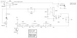
My GP1U52X has no output. I need to get something working today for a project. Has anyone made a demodulator from an IR detector and a 567 tone decoder or a PLL? Don't want to spend all day designing one if there is a circuit around that has been proven to work.
 

Dippy

Moderator
Dead sure it's dead? 'scoped it?

I haven't made what u are on about, but I just want to make sure of terminology; when you say "..an IR detector " are you talking about an I/R photodiode component, or photodiode+built-in-amp receiver?

If you are talking about a simple photodiode then you will need plenty of amp/filtering before the 'tone' can be decoded. eg the good old TBA2800 or some fancy work with op-amps.
 

hippy

Technical Support
Staff member
The GP1U52X seems to be similar to the TSOP IR Receiver used by PICAXE but 40kHz. I imagine you could build something equivalent out of discrete parts but I'd have no idea how to. Google / AltaVista may be your best bet.

As a stop-gap you could perhaps find a 0V and unmodulated signal in your remote and hard-wire that into where the demodulated GP1U52X signal went, or maybe program up a PICAXE to generate the correct bit-stream ?
 

Mike Rettig

New Member
I'm trying to look at signals from about 5 IR remotes for tv/vcr/dvd, etc. Center freq needs to be 38khz. I can breadboard op amps, filters, etc - and I already looked on the web but couldn't find anything. Just seemed cheaper to make one then drive all over town looking for another module.
 

gengis

New Member
Designed this some years ago . . . it is a break beam photo detector. I used the center freq of the PLL to excite the LED and used the same PLL to differentiate the signal - for noise immunity.

Response is relatively (50ms) slow but can be made fast by attenuating the peak signal into the PLL with a diode (cathode to ground) at the input and a limiting resistor from the 4049 output string. You'd need to tune it for your center frequency and wouldn't need the LED circuit.

Another possible source of problems it has no "swamping" protection - DC feedback on the detector transistor to make it sensitive to changes over a wide dynamic range - like sunlight or bright light shining directly into the photo transistor so you'd need an IR filter or some feedback to actively bias the transistor - normal indoors room lighting was no problem.

For some reason my schematic capture and photo editor aren't cooperating this morning so the 567 box is wrong.

I did another version that used op amps in the amplifier with a band pass filter but it used more parts and was only marginally better than the inverter amp.
 

Attachments

hippy

Technical Support
Staff member
As the deadline has gone and passed, I think the best solution is to simply pay the few dollars it costs for an exact replacement part.
 
Top