Quite alot of questions

SilentScreamer

Senior Member
Hi all,

I've got a few questions relating to two PICAXE projects I currently have.

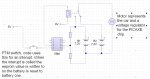
The first is monitoring a 7.2V battery (six 1.2V cells) on an electric remote control car and when it drops below a specific voltage (as yet to be decided) it will switch one relay off and turn the another on (to swap from one battery to another).

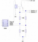
I thought about using an 08M and running the 7.2V battery through a voltage regulator. For the time that there is no battery (the competition rules state only one battery can be used else I would use them in parallel) I plan to use a capacitor to keep the power to the 08M. For monitoring the battery (only one needs to be monitored) I thought about using the ADC and then connecting 2 output pins

So my questions:
1) Does this sound like the best method of doing it or is there a better way?
2) What value capacitor would be suitable? I've found cheap ones that are 22000uF at rapid would this be too large or small? (I have very little knowlage of capacitors other that using them to fade LEDs as they turn off on breadboards)
3) Should I use a voltage reference on another ADC pin? Or have I misunderstood how to use voltage references?
4) Would this relay require a transistor or could I run it directly (I cant find a datasheet for it but I think it will use about 0.1A? (P/V=I therefore 0.51/5=0.102Amp)?

The other project is to make a clock with multiple chips (I currently plan the real time clock chip that technology supplies stock, a main 28X1 and also 2 additional PICAXEs to run twelve 7 segment displays). I want to do this project so I can simply learn more about I2C and getting PICAXEs to work together via serial.

So my questions:
5) To run the 7 segment displays I was going to use 28X1s to multiplex them (6 displays per X1, with 8 outputs used connected to each displays sections then one output directly connected to the cathode of each display, when I make the pin low it will allow current to flow into it and make a circuit). Would this work? Or is there a better way?
6) Is there a cheaper chip that would work (28X maybe?) for running six displays without running out of memory? Or should I just write the code then buy the chips? Or would it even be possible to use an 28/40X2 to run all 12 displays from one chip? I don't understand the X2's labelling in the manuals.

Thanks in advance for any help given :)
 
Last edited:

inglewoodpete

Senior Member
Quite seriously SS, you are wanting to jump into quite involved projects but are asking questions that suggest you are on an earlier part of the learning curve.

Your ideas have merit, don't get me wrong. I suggest you start small, one project at a time.

You will probably have difficulty buying a 28X now: they went out of production about 2 year ago. The 28x1 is a superior chip and has up to 16 outputs if port C is configured as all outputs. Since you want to multiplex the 7-segment displays, have a look at the 74LS138 3-to-8 decoder. 2 of these would drive 12 common-cathode 7seg displays using just 7+4 PICAXE output pins. However, by the time you cycle through 12 7-segment displays with a PICAXE, flicker may be a problem. Clocking the PICAXE up to 8 or 16MHz may overcome this.

7-segment displays, especially 12 of them, can be a relatively expensive way to display numbers. Would an 2x16 LCD display be more cost effective? Either way, start small and build up: lets say a 28x1 and a couple of 7 seg displays. Get them working how you want and then make decisions on how to continue.
 

Dippy

Moderator
Sounds also like you haven't read any PICAXE Data Sheets either.
e.g. Manual 1 Page 7 "At a Glance Specifications".
"Each output can sink or source 20mA."

Then you will realise that you need a transistor.
For most relays you will.

Now that you know that you can look through the MANUALs to where it shows an example of how to connect a transistor to switch a relay.
Read it carefully.

Onto powering PICAXE from 7.2V batteries via a relay and measuring Battery Voltage.
Perfect in theory.
Several things to note:
Regulators have a dropout voltage. This is like a bit of voltage 'headroom' that a regulator needs.
No doubt you will be looking at the old 7805 Dinosaur. Cheap innit? I wonder why.
Check out the dropout V. Add it to 5V. What do you get?

So, your 7.2V batteries may only be part used before the BatteryV cannot provide eough headroom. So, your regulator 5V out will droop. So, your battery monitoring ADC reference will droop.

Partial solution. For PICAXE supply choose a reg with very low dropout. Though still not really ideal as there will be transients around.

There are solutions but I think you need to read and absorb a bit first.

If you get a grip on the basics here then you will understand other people's solutions.

PS. Is this a school project that will be marked?
 
Last edited:

SilentScreamer

Senior Member
Sounds also like you haven't read any PICAXE Data Sheets either.
e.g. Manual 1 Page 7 "At a Glance Specifications".
"Each output can sink or source 20mA."

Then you will realise that you need a transistor.
For most relays you will.

Now that you know that you can look through the MANUALs to where it shows an example of how to connect a transistor to switch a relay.
Read it carefully.

Onto powering PICAXE from 7.2V batteries via a relay and measuring Battery Voltage.
Perfect in theory.
Several things to note:
Regulators have a dropout voltage. This is like a bit of voltage 'headroom' that a regulator needs.
No doubt you will be looking at the old 7805 Dinosaur. Cheap innit? I wonder why.
Check out the dropout V. Add it to 5V. What do you get?

So, your 7.2V batteries may only be part used before the BatteryV cannot provide eough headroom. So, your regulator 5V out will droop. So, your battery monitoring ADC reference will droop.

Partial solution. For PICAXE supply choose a reg with very low dropout. Though still not really ideal as there will be transients around.

There are solutions but I think you need to read and absorb a bit first.

If you get a grip on the basics here then you will understand other people's solutions.

PS. Is this a school project that will be marked?
It isn't going to be marked, it is for the formula schools challenge. I've helped out for years with it at my school, now with my GCSEs I cant help so much and they now have money and people so I'm not particually needed anymore. I have previously asked questions about my GCSE but have always stated that it was for GCSE (asking people is generally better than google for getting useful information); my project is/was an alarm system that has a 28X1, a 4 digit reprogrammable code, an LCD display and the firmware chip for it. This is just for fun, I enjoy electronics and I'm disappointed I can't continue to A level. (I always do my own homework. :))

your 7.2V batteries may only be part used before the BatteryV cannot provide eough headroom. So, your regulator 5V out will droop.
I have a regulator that requires 6.2V so the 7.2V should be plenty. I think the batteries need to be changed at around 6.5V so it should never droop).

flicker may be a problem. Clocking the PICAXE up to 8 or 16MHz may overcome this.
I have some 20Mhz resonators on order currently, these should overcome this I believe?

Would an 2x16 LCD display be more cost effective?
Yes, but I have used these before so I can't see the point in using them further unless I'm making the project for a reason.

So, your battery monitoring ADC reference will droop.
Could I combat this by having a voltage reference (I'm thinking of getting this even though its surface mount) and doing math on the chip?

I have read the sheets to a point, though I'm miles away from being thorough.
 

eclectic

Moderator
@SS
Motors and relays.

1. What is the current draw for the car motors?
(Normal and stall)?

2. The small Rapid relay has a 3A capability.
Is this enough for a competition car?

3. “Ordinary” relays consume current, adding to battery drain.
Is there enough cash to go to a higher rated
Latching relay?

e
 

SilentScreamer

Senior Member
I think I might be being optimistic about the current drain of the motors (I can't check until monday) however how much would it be for a latching relay apprimatly? (I think it could need to be 10A (from a quick google search) maybe more, I've always dealt with the petrol cars so the electric are rather alien to me beyond putting them together)
 

hippy

Ex-Staff (retired)
On battery monitoring a 3V3 LDO will help there, and, as long as the PICAXE supply doesn't drop below that, a simple voltage divider from 7V2 should allow READADC10 and a hard-wired value to determine if good or bad, no external voltage reference needed. You might even be able to get away with a pot or a couple of resistors and use a digital schmitt input, simply read the input pin as battery okay or not.

The PICAXE can last quite some time on just capacitor power under the right circumstances, but you'll have to experiment. You may not need an excessively huge capacitor. A capacitor alone won't give the voltage headroom nor current to power a relay. That could be an interesting challenge to solve and stay within the only one battery rule.
 

SilentScreamer

Senior Member
On battery monitoring a 3V3 LDO will help there, and, as long as the PICAXE supply doesn't drop below that, a simple voltage divider from 7V2 should allow READADC10 and a hard-wired value to determine if good or bad, no external voltage reference needed. You might even be able to get away with a pot or a couple of resistors and use a digital schmitt input, simply read the input pin as battery okay or not.

The PICAXE can last quite some time on just capacitor power under the right circumstances, but you'll have to experiment. You may not need an excessively huge capacitor. A capacitor alone won't give the voltage headroom nor current to power a relay. That could be an interesting challenge to solve and stay within the only one battery rule.
If latching relays can't be used could this be sloved by having one normally open relay and another normally closed one. Before the power is switched the chip writes to eeprom, then when the power comes back the chip will read the eeprom and if contains 1 then don't power the relays, if it contains a 0 then power them?
 

Dippy

Moderator
I don't quite follow.
Can you draw that? ( A good drawing save lines of words).

The whole point of a latching relay is that you only have to power them briefly.
I just hope no-one mentions FETs.
 

SilentScreamer

Senior Member
The idea was for non latching relays.

I have 2 relays attached to two output pins (via transistors obviously). If the cuircuit isn't powered then the 2nd battery is in use.

Before disconnecting the battery the chip will write to the eeprom the in the code when the chip first runs it will read the eeprom to see if battery one or two should be in use. If battery two should be in use it does nothing. If battery one is in use then it powers both relays.

This would drain battery one quicker but battery two slower. If drain was found to be an issue it could be powered by additonal battery though this would add additional space which will be an issue (the extra battery will be hard to find room for without having two extra batteries).
 

Dippy

Moderator
Shouldn't you factor in the battery condition when 'choosing' which battery to select.

If you're happy with it then go for it, but sounds a little power wasteful to me. But then, only you know what conditions and durations you'll be using it for.

I think a little schematic would be helpful if you're expecting help/suggestions from others.
At this time of year our crystal balls are very cold ;)
 

SilentScreamer

Senior Member
Race is twenty minutes or might even be 15 (I forget:confused:) and i'm working on a sceamatic as I type. (i'm not used to laptop mice so im slow)
 
Last edited:

SilentScreamer

Senior Member
A possible new idea (see attached schematic).

The code would then go something like this (I know the sytax will probably be wrong but its a rough plan of what it would be).

Code:
symbol Relay = pin0
symbol ADCBattery1 = w1
symbol ADCBattery2 = w2

Main:
        read b0,b1
        if b1=1 then
                goto Battery1
        else if b1=0 then
                goto Battery2
                endif

Battery1:
        readadc10 1,ADCBattery1
        readadc10 3,ADCBattery2
        let w3 = ADCBattery1/10
        let ADCBattery1 = ADCBattery1-w3
        if ADCBattery2>ADCBattery1 then
                let b1 = 0
                write b0,b1
                high Relay
                endif
        pause 1000
        goto Battery1

Battery2:
                readadc10 1,ADCBattery1
                readadc10 3,ADCBattery2
        let w3 = ADCBattery1/10
        let ADCBattery2 = ADCBattery2-w3
        if ADCBattery1>ADCBattery2 then
                let b1 = 1
                write b0,b1
                high Relay
                endif
        pause 1000
        goto Battery2
Any suggestions on improvements or corrections?

Thanks again for all help; past and future.
 

Attachments

Last edited:

kevrus

New Member
Its 2am, i'm on nightshift, blurred vision and my brain is foggy. I had a quick glance at your code....are you trying to automatically switch batteries when the voltage drops by 10% on the batt in use?

If so, I can't see how the code goes from battery2 to battery1, and by subtracting w3, it looks to me as though the battery 'in use' will immediately be 'lower' than the standby battery.

Modifying your code, would this work?
Or maybe i'm talking nonsense.....:)

Code:
 symbol Relay = 0
symbol ADCBattery1 = w1
symbol ADCBattery2 = w2

Main:
read b0,b1
        if b1=1 then Battery1
        goto Battery2


Battery1:
high Relay
       do
        readadc10 1,ADCBattery1
        readadc10 3,ADCBattery2
        let w3 = ADCBattery1/10                           'makes w3 equal to 10% of battery 1 voltage...(is 10% enough?)
        let ADCBattery1 = ADCBattery1+w3             'adding w3 allows batt 1 voltage to fall by w3 value before switching
        if ADCBattery2>ADCBattery1 then battery2   'if batt 2 is now greater than batt 1 then switch to reserve 
        let b1 = 0
        write b0,b1
        pause 1000
       loop


Battery2:
low Relay
      do
       readadc10 1,ADCBattery1
       readadc10 3,ADCBattery2
       let w3 = ADCBattery2/10
       let ADCBattery2 = ADCBattery2+w3
       if ADCBattery1>ADCBattery2 then Battery1
       let b1 = 1
       write b0,b1
       pause 1000
      loop
Note, it will keep looping from one batt to the other as the voltage drops so this may need looking at...
 
Last edited:

inglewoodpete

Senior Member
SS: I suggest you run the control circuitry (LDO regulator, PICAXE and relay) from the second battery. When the first battery fails, the PICAXE can release the relay and share its battery with the motor. This overcomes most problems you could encounter when switching to the second supply.

Also, make sure your motor and logic common rails are kept separate all the way to the battery negatives. Motor noise in the 0v rail can easily restart the PICAXE.
 

SilentScreamer

Senior Member
Thanks that is what the code should do (and the commenting and syntax corrections). I wanted it to check when it was 10% (or some other value that will have to simply be experimented with in practice, but 10% is a nice number to start with) lower that the other battery (lower = subtract in my head :p).

I intend it to loop from one battery to the other so that we're always using the best battery we have on the car (until they're both useless which will be when we need to head to the pit and change them both, but should be half the number of stops and from past years 2 batteries are enough).

Also the if statement in both the Battery loops shouldn't just change from one to another as when the relay switches (I'm going to try and use a latching one) the PICAXE will lose power, therefore it writes to the eeprom about which battery to use.

Seeming as I no longer need to subtract I can do this to stop using w3?

Code:
symbol Relay = 0
symbol ADCBattery1 = w1
symbol ADCBattery2 = w2

Main:
read b0,b1
        if b1=1 then Battery1
        goto Battery2


Battery1:
high Relay
        do
        readadc10 1,ADCBattery1
        readadc10 3,ADCBattery2
        let ADCBattery1 = ADCBattery1 / 10 + ADCBattery1       'makes the battery 2 value 10% larger
        if ADCBattery2>ADCBattery1 then                           'if batt 2 is now greater than batt 1 then switch to reserve 
                let b1 = 0
                write b0,b1
                endif
        pause 1000
        loop


Battery2:
low Relay
       do
       readadc10 1,ADCBattery1
       readadc10 3,ADCBattery2
       let ADCBattery2 = ADCBattery2 / 10 + ADCBattery2
       if ADCBattery1>ADCBattery2 then
               let b1 = 1
               write b0,b1
               endif
       pause 1000
       loop

EDIT: Just a quick thought? Could an issue arise with the variable overflowing? If so will it be better to take 10% off the other battery rather than add it to the current one?
 

SilentScreamer

Senior Member
SS: I suggest you run the control circuitry (LDO regulator, PICAXE and relay) from the second battery. When the first battery fails, the PICAXE can release the relay and share its battery with the motor. This overcomes most problems you could encounter when switching to the second supply.

Also, make sure your motor and logic common rails are kept separate all the way to the battery negatives. Motor noise in the 0v rail can easily restart the PICAXE.
That does sound like a far better idea. I'll make that on a breadboard to test it and get back if any issues arise (no doubt as a result of me :D).

Thanks all for the help again.
 

Dippy

Moderator
Michael... don't ;)

I like IPs idea.

Assuming Battery 2 always starts in tiptop condition and that it never droops down to PICAXE+V + Dropout V all should be OK.

Comments on circuit:-

1. Put a small capacitor at the ADC points to RC any spiky nasties. i.e. a low-pass filter. If you notice wobbly ADC values when motor running this could be the reason. if it does happen then you may have to experiment with cap values and types, but I'd have guessed that 47nF to 100nF of ceramic cap would help.
NOTE: if your battery to motor is PWM controlled then you may have some transient dips that take the battery (briefly) below your desired threshold. So, maybe larger caps needed and/or a few ADC readings averaged. Unless in a hurry I'd always take several ADC readings and do an average.

2. Put a couple of caps //d right next to PICAXE power pins (as physically close as possible). E.g. 22nF to 100nF ceramic //d with a 22u to 100u elect.
For good operation, and particularly ADCing, it is crucial to have nice smooth stuff supplying PICAXE.

3. Your measurement of battery (Via the 10k res):-
The 'sense' wire/track must connect to the battery connection be as close as possible to the battery terminal. Otherwise your measurment may inadvertently 'include' IR drop in wires/tracks which is not good.

4. As alluded to by IP. Big fat earth/ground should be used on your PCB. If using stripboard then double-up the ground strip. Weedy grounds can produce undesired effects.

Good luck.
 

Dippy

Moderator
Yes. Parallel-ed.
Sorry, sloppy shorthand.

Recently I was doing a device which ADCd (oops done it again) a sensor.
Results were awful. Added cap at PIC + terminal (other side of cap to ground), really close - results blooming excellent.
(In my case it was an issue with an LP2950 regulator o/put but it brought home how crucial things can be particularly when needing good ADC measurements).
 

SilentScreamer

Senior Member
Does this look okay?

Code:
#PICAXE 08M

symbol Relay = 0
symbol ADCBattery1a = w1
symbol ADCBattery1b = w2
symbol ADCBattery1c = w3
symbol ADCBattery2a = w4
symbol ADCBattery2b = w5
symbol ADCBattery2c = w6

Battery1:
high Relay
	do
		'Read ADC 3 times
		readadc10 1,ADCBattery1a
		readadc10 2,ADCBattery2a
		pause 1000
		readadc10 1,ADCBattery1b
		readadc10 2,ADCBattery2b
		pause 1000
		readadc10 1,ADCBattery1c
		readadc10 2,ADCBattery2c
		'Average the results for pin1
		let ADCBattery1a = ADCBattery1a / 3
		let ADCBattery1b = ADCBattery1b / 3
		let ADCBattery1c = ADCBattery1c / 3
		let ADCBattery1a = ADCBattery1a + ADCBattery1b + ADCBattery1c
		'Average the results for pin2
		let ADCBattery2a = ADCBattery2a / 3
		let ADCBattery2b = ADCBattery2b / 3
		let ADCBattery2c = ADCBattery2c / 3
		let ADCBattery2a = ADCBattery2a + ADCBattery2b + ADCBattery2c
		'Remove 10% from the 2nd battery's average
		let ADCBattery2b = ADCBattery2a / 10
		let ADCBattery2a = ADCBattery2a - ADCBattery2b
		'Does it need to change battery?
		if ADCBattery2a>ADCBattery2a then Battery2
		pause 5000
	loop

Battery2:
low Relay
	do
		'Read ADC 3 times
		readadc10 1,ADCBattery1a
		readadc10 2,ADCBattery2a
		pause 1000
		readadc10 1,ADCBattery1b
		readadc10 2,ADCBattery2b
		pause 1000
		readadc10 1,ADCBattery1c
		readadc10 2,ADCBattery2c
		'Average the results for pin1
		let ADCBattery1a = ADCBattery1a / 3
		let ADCBattery1b = ADCBattery1b / 3
		let ADCBattery1c = ADCBattery1c / 3
		let ADCBattery1a = ADCBattery1a + ADCBattery1b + ADCBattery1c
		'Average the results for pin2
		let ADCBattery2a = ADCBattery2a / 3
		let ADCBattery2b = ADCBattery2b / 3
		let ADCBattery2c = ADCBattery2c / 3
		let ADCBattery2a = ADCBattery2a + ADCBattery2b + ADCBattery2c
		'Remove 10% from the 21st battery's average
		let ADCBattery1b = ADCBattery1a / 10
		let ADCBattery1a = ADCBattery1a - ADCBattery1b
		'Does it need to change battery?
		if ADCBattery1a>ADCBattery2a then Battery1
		pause 5000
	loop
 

Attachments

nickpatts

Member
couldn't you just use the two batterys and a relay?, (may need a third power source to active relay at start to switch battery 1 as source) but wire it up so when relay is on it is getting powered by battery one, then when the battery dies, the relay on dies and so switches back to battery 2?. battery 2doesn't need to be powering the relay in any way just its normal function.

you may have to put something in place so the replay fails at particular voltage.

haven't explained it well, but hope you get the idea, its abit power wasted keeping the replay on, but very simple.


sorry and i didn't use a picaxe.
 

Dippy

Moderator
Only a quick look:

Always do your summing before division when the sum doesn't overflow (and it won't in this case).

Don't know what regulator you plan to use, but PLEASE look at the Manufacturer's Data sheet about the cacpacitors needed for the regulator.

I can't follow your transistor/PIC/Relay conenction.
Make life easy and COPY the one out of the manual. Didn't I suggest this before??
READ, READ ,READ..... as my clarinet teacher used to say.

With a bipolar transistor in the normal config, you must have a resistor to the base.
Is there a 'problem' with the example given in MANUAL 1 page 56 (of the current on-line manual)??
 

SilentScreamer

Senior Member
I did the transistor circuit from memory and remembered it incorrectly. I've just corrected it and also added the protection diode.

I thought it would overflow (I've only just worked out that 10 bit = 1023) therefore I did the division first.

I don't yet know which regulator or which transistor I will be using (I'm sure we have some at school, but there specification could be anything), therefore I don't yet know the value of the capacitors for the regulator or value of the base resistor.
 

Attachments

Last edited:

kevrus

New Member
SilentScreamer
just one thing ive noticed from Battery1 routine...should
Code:
if ADCBattery2a>ADCBattery2a then Battery2
read as

Code:
if ADCBattery2a>ADCBattery1a then Battery2
 

SilentScreamer

Senior Member
I've just found out a major problem. Out new speed controller takes 30 seconds to "load". Therefore the car cannot lose power even for a tenth of a second, is there any way a capacitor could be realistically used to provide (a guess at the typical current drain (according to a battery lasting 8 minutes on a 3300mA battery which is about normal) is 25A unless I've miscalculated it :() power while the relay is being switched?
 

Andrew Cowan

Senior Member
The speed controller can operate with a noisy motor, so it will probably have big capacitors inside (on the 5V side of its 5V regulator)(if it is microcontroller based).

You just need to keep the chip in the speed controller powered - not the motor.

A
 

SilentScreamer

Senior Member
So is it sensible to hope that the speed controller can keep itself running for the tiny amount of time the car has no power? Or does this involve stripping down the speed controller? :eek:
 

Andrew Cowan

Senior Member
You can only tell by trying.

The time taken for a relay to switch is very small - I imagine it would be able to keep itself running.

A
 
Top